Page
2
of
8
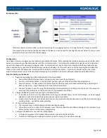
Radio Base LEDs
The Base contains a button which is used primarily to perform a paging function. Pressing the button causes an audible
tone signal to be emitted by the Reader linked to the Base and can be used for locating the scanner when it is active –
press
quickly (less than one second) to initiate paging
.
Configuration
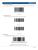
The Reader is factory-configured with a standard set of default features. After scanning the Interface barcode, you can select other
options to customize your Readers behavior with The Uniform Solution. This will be accomplished through the use of instructions
issued to the Reader through programming barcodes. Some instructions require that only a single barcode be scanned whereas
others required that a sequence of barcodes be scanned by the Reader. For the most part you will be scanning the barcodes that
follow in their order of appearance. Simply read then follow the instructions below. –
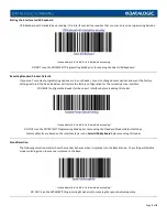
Note that in the last section, the Unlink
programming barcode is only to be used when attempting to reestablish a connection between a Reader and its Base Station
.
Steps for Setting up the Reader
1.
Begin by connecting the USB Interface Cable to the Base Station
•
Consult the Quick Reference Guide –
properly orient and insert the cable firmly
•
You can use the Base Station in the horizontal position right out of the box without any adjustments
•
Exercise Caution – its heavy plastic, but plastic breaks > exercise some care when manipulating or adjusting the
Base configuration –
rough handling is not covered by the warranty
•
Connect the Base to your PC using the USB Interface Cable, preferably to a USB port on the back of the computer…
avoid use of the USB ports on the front of the PC for hardware connections
2.
Charge the Reader (Scanner) by placing it in the Base Station
•
It can take up to 22 hours in the Base Station to charge w/ USB Host Power from a full discharge –
no power supply
adapter is needed, but a Datalogic optional power supply is available
•
Simply return the Reader to the Base when not in use and you should not experience any difficulty in maintaining a
working charge –
see battery notes preceding
3.
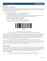
Set the Interface Selection
•
The Interface Type is USB Keyboard with Standard Key Encoding
•
You will also want to confirm that the Reader is set to the Standard Product Default Settings for the Interface Type
before further feature customization programming
4.
Configure the Reader for use with the USW program
•
A single setting governs the Readers behavior when placed in the Base Station
•
A number of settings are employed to ensure optimal accuracy of reads when scanning


