GWY-01-PBS-01
40
5
5.3 DATA EXCHANGE
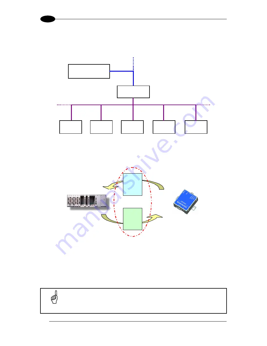
The Master Profibus is usually a PLC (Siemens S7 or others) but it could be a PC based
device as well. The Gateway Profibus is always Slave in the Profibus network.
PLC
RFID
Controller
RFID
Controller
RFID
Controller
RFID
Controller
RFID
Controller
GWY-01-PBS-01
Subnet16™ Network
Profibus Network
Profibus Master
Profibus Slave
Figure 19: Profibus-DP Network Diagram
Basically two shared memory areas (Exchange Areas) are used to exchange information
between the SLAVE and the MASTER, both devices provide information to each other.
INPUT
AREA
OUTPUT
AREA
PLC GWY-01-PBS-01
Write
Read
Write Read
Exchange Areas
Master Slave
Figure 20: Profibus Communication – Data Exchange Areas Diagram
Input and output areas always refer to the Master: this means that the Gateway writes to the
Input buffer and the PLC writes to the Output buffer.
The dimension of the exchange areas can be set to different values by the PLC through the
GSD file: the Gateway Profibus allows up to
152 bytes as a combined total of the Input
and
Output Areas
.
NOTE
For further information regarding Fieldbus interfacing including
downloadable support files, go to the HMS website at
http://www.anybus.com, choose the link to the support page, select the
Anybus-CompactCom product type
and then your
network type
.
Summary of Contents for GWY-01-PBS-01
Page 1: ...GWY 01 PBS 01 Reference Manual ...
Page 5: ...v C ASCII CHART 92 ...
Page 101: ...www automation datalogic com ...


