background image

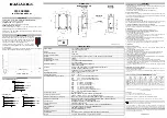
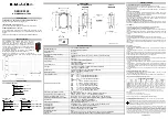
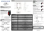
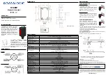
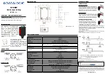
S100W

Manuale Istruzioni


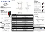
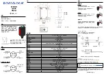
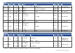
CONTROLLI

LED DI USCITA (giallo)

Il LED giallo indica lo stato dell’uscita.

Si veda “Regolazioni” per le modalità di utilizzo.

INSTALLAZIONE

L’installazione  del  sensore  può  essere 

effettuata grazie ai due fori filettati (M3) 

sulla parte frontale del corpo, tramite 

due viti (M3x12 o di maggiore lunghezza 

oppure M2.5 passanti, coppia max. di 

serraggio 0.4 Nm) con rondelle e grazie 

alle due asole posteriori tramite due viti 

passanti (M3, coppia max. di serraggio 

0.4 Nm).

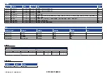
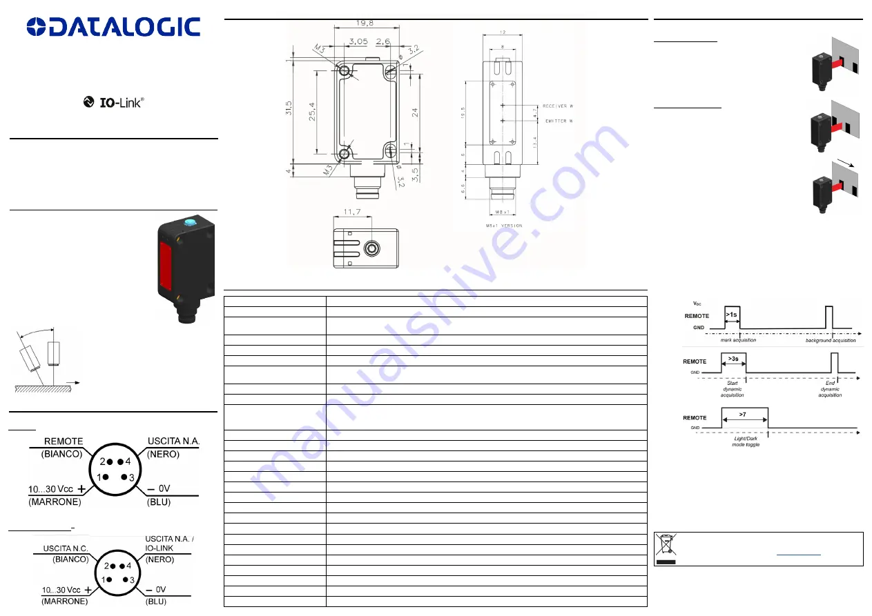
CONNESSIONI

DIMENSIONI

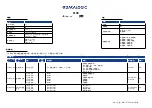
DATI TECNICI

Tensione di alimentazione

10 … 30 Vcc (Classe 2 UL508) (protetta contro l’inversione di polarità)

Tensione di ripple

10% max.

Assorbimento

(esclusa corrente di uscita)

35 mA max

Uscite / Uscita di Allarme

PNP or Push-Pull (protezione contro il cortocircuito).

Corrente di uscita

100 mA max. (per entrambe le uscite, protezione al sovraccarico)

Tensione di saturazione dell’uscita

≤ 2 V

Ingressi

Il REMOTE (S100W-..-PK)/pin 2 può essere configurato come ingresso REMOTE tramite IO-Link (S100-..-OZ).

L’ingresso non può essere lasciato sconnesso.

Tempo di risposta

25 μs

Frequenza di commutazione

20 kHz

Tipo di emissione

blu (465 nm) / verde (520 nm) / rossa (630 nm) 

con selezione automatica

Gruppo di Rischio esente (RG0) per IEC 62471

Dimensione minima dello spot

6.5 mm x 1.5 mm

Distanza operativa (valori tipici)

12,5 mm

Profondità di campo

±  2 mm

Selezione BUIO/LUCE

automatica

Indicatori

LED DI USCITA (giallo)

Temperatura di funzionamento

-25 … 55 °C

Temperatura di immagazzinamento

-40 … 70 °C

Rigidità dielettrica

 : 1500 Vca 1 min tra parti elettroniche e contenitore

Resistenza d’isolamento

>20 MΩ 500 Vcc tra parti elettroniche e contenitore

Reiezione alla luce ambiente

come prescritto da EN 60947-5-2

Vibrazioni

ampiezza 0.5 mm, frequenza 10 … 55 Hz, per ogni asse (EN60068-2-6)

Resistenza agli urti

11 ms (30 G) 6 shock per ogni asse (EN60068-2-27)

Materiale contenitore

Corpo ABS, Gemma PMMA

Materiale lenti

finestra frontale in PMMA; lente in PC

Protezione meccanica

IP67

Collegamenti

connettore M8 a 4 poli

Peso

12 g. max. versione a connettore

REGOLAZIONI

S100W - Ingresso REMOTE

Con il segnale REMOTE si possono eseguire le funzioni di acquisizione da 

remoto senza l’uso dell’IO-Link.

Impostare l’uscita N.C. come ingresso REMOTE tramite IO-Link.

Datalogic S.r.l.

Via S. Vitalino 13 - 40012 Calderara di Reno - Italy

Tel: +39 051 3147011 - Fax: +39 051 3147205 - www.datalogic.com

Link utili disponibili su www.datalogic.com: Contatti, Termini e Condizioni, Supporto.

Il  periodo  di  garanzia  per  questo  prodotto  è  di  36  mesi.  Per  maggiori  dettagli  vedere 

Condizioni Generali di Vendita.

Per  informazioni  sullo  smaltimento  delle  apparecchiature  elettriche  ed 

elettroniche (WEEE) consultare il sito Web 

www.datalogic.com

.

© 2020 Datalogic S.p.A. e/o le sue consociate - TUTTI I DIRITTI RISERVATI. - Senza con ciò limitare i diritti coperti 

dal copyright, nessuna parte della presente documentazione può essere riprodotta, memorizzata o introdotta in un 

sistema di recupero o trasmessa in qualsiasi forma o con qualsiasi mezzo, o per qualsiasi scopo, senza l’espresso 

consenso scritto di Datalogic S.p.A. e/o delle sue consociate. Datalogic e il logo Datalogic sono marchi registrati 

di Datalogic S.p.A. depositati in diversi paesi, tra cui U.S.A. e UE. Tutti gli altri marchi registrati e brand sono 

di proprietà dei rispettivi proprietari. Datalogic si riserva il diritto di apportare modifiche e/o miglioramenti senza 

preavviso.

821006951 Rev. B

Dimensioni in mm

La  distanza  operativa  è  misurata 

partendo  dalla  superficie  frontale 

dell’ottica del sensore.

La  rilevazione  di  tacche  su  materiali 

riflettenti può essere migliorata fissando 

il  sensore  in  modo  che  la  direzione  di 

lettura sia inclinata di 5°…20° rispetto 

alla normale.

S100W

S100W IO-LINK

®

ACQUISIZIONE FINE

Rilevazione della tacca

La  modalità  operativa  BUIO/LUCE  è  selezionata 

automaticamente dal sensore.

Posizionare la tacca in coincidenza dello spot del 

sensore  e  inviare  il  comando  IO-Link.  Il  sensore 

acquisisce alternando le emissioni rossa, verde e 

blu.

Non muovere la tacca durante questa fase.

Rilevazione dello sfondo

Posizionare lo sfondo in coincidenza dello spot del 

sensore  e  inviare  il  comando  IO-Link.  Il  sensore 

acquisisce alternando le emissioni rossa, verde e 

blu.

Non muovere lo sfondo durante questa fase.

ACQUISIZIONE DINAMICA

Usare  l’acquisizione  dinamica  per  acquisire 

tacche in movimento. Il sensore rileva il contrasto 

fra la tacca e lo sfondo in movimento e imposta 

automaticamente il valore della soglia. È 

necessario impostare preventivamente la modalità 

LUCE/BUIO.

ACQ.

Se  il  LED  lampeggia  lentamente  l’acquisizione  è  fallita  per  insufficiente 

contrasto.  Premendo  il  tasto  SET  il  sensore  ritorna  nella  impostazione 

precedente. Ripetere la procedura dall’inizio.

Verificare sul process data lo stato dell’acquisizione.

I sensori NON sono dispositivi di sicurezza, quindi NON devono essere 

utilizzati per la gestione di sicurezza delle macchine sulle quali sono 

installati.

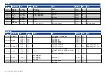
Summary of Contents for IO-Link S100 Series

Page 1: ...T LED changes its status once If the object is out of range the sensor fails the acquisition and the OUT LED blinking To return at normal operation connect the REMOTE VDC for 100ms Acquisition for bac...

Page 2: ...tivo 2 Collegare il filo REMOTE a Vcc per 1 s Il LED OUT cambia stato 1 volta Se l oggetto fuori dal campo operativo il sensore fallisce l acquisizione e il LED OUT lampeggia Per tornare in funzioname...

Page 3: ...LED OUT blinkt Zur R ckkehr zum Normalbetrieb REMOTE mindestens 100 ms lang mit VDC verbinden Erfassung f r Hintergrundausblendung 1 Den Sensor vor dem Hintergrund platzieren innerhalb der maximalen...

Page 4: ...est hors de port e le d tecteur ne peut pas effectuer l acquisition et la LED DE SORTIE clignote Pour revenir au mode de fonctionnement normal relier REMOTE Vcc pendant au moins 100ms Acquisition pour...

Page 5: ...REMOTE S100 M10 T10 REMOTE M10 T10 S100 M10 1 2 REMOTE VDC 1 OUT LED OUT LED REMOTE VDC 100ms 1 2 REMOTE VDC 3 OUT LED OUT LED REMOTE VDC 100ms S100 T10 1 2 REMOTE VDC 1 OUT LED OUT LED REMOTE VDC 100...

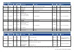
Page 6: ...el index 0x3A System Parameters Index dec Parameter Object Name Lenght Subindex offset Value Range Description Data Type Access 0x000C 12 Device Access Locks 2 octets Bit 1 Data Storage 0 unlocked 1 l...

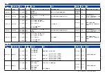
Page 7: ...perature 2 octets 2 octets 2 octets 2 octets 2 octets 1 64 2 48 3 32 4 16 5 0 Device temperature actual Device min temperature since powerup Device max temperature since powerup Device min temperature...

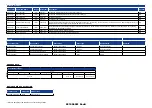
Page 8: ...distance M10 Switching threshold B10 T10 UIntegerT R W Saved in non volatile memory B10 T10 setting a higher threshold reduces the operating distance progressively to 0 output always active 0x003F 63...

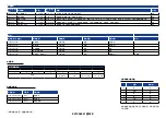
Page 9: ...t type Device status Remarks 0x4220 16928 Temperature underrun Appears Disappears Warning Out of specification 0x4210 16912 Temperature overrun Appears Disappears Warning Out of specification 0x5100 2...

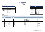
Page 10: ..._1 ISDU ISDU 0xC 0x3A 0x000C 12 2 1 0 1 0 1 2 3 4 15 RecordT R W 0x000D 13 2 2 2 2 2 2 0x0001 0x8000 0x8001 0x8003 0x8004 0x8007 SSC UIntegerT16 ArrayT RO 0x000E 14 PDInput 3 3 3 3 0x01 0x01 0x00 0x01...

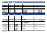
Page 11: ...0 0 StringT RO 0x0018 24 32 B10 T10 StringT R W 0x0028 40 1 PDin RO 0x0052 82 2 2 2 2 2 1 64 2 48 3 32 4 16 5 0 IntegerT IntegerT IntegerT IntegerT IntegerT RO RO RO RO RO 0x0053 83 2 2 1 16 2 0 B10...

Page 12: ...T10 UIntegerT 0x003E 62 SSC2 2 2 1 16 2 0 0 3983 M10 210 1982 B10 177 1783 T10 M10 B10 T10 UIntegerT R W B10 T10 0 0x003F 63 SSC2 1 1 1 24 2 16 0x00 B10 T10 0x01 M10 0x01 DO UIntegerT UIntegerT R W T1...

Page 13: ...B10 T10 SSC1 SSC2 RGB B10 T10 WO 0x0002 2 1 0xA5 165 WO 0x0002 2 Ping 1 0xAF 175 LED WO 0x4220 16928 0x4210 16912 0x5100 20736 0x7710 30480 0x8C40 35904 B10 ID S100 PR 5 B10 OZ 10001 S100 PR 5 T10 OZ...

Page 14: ...DR CKLICHEN STILLSCHWEIGENDEN GESETZLICHEN ODER GARANTIE Datalogic garantit que les Produits seront exempts de d fauts de mat riaux et de fabrication dans le cadre d une utilisation normale et appropr...

Page 15: ...ahmen zu ergreifen FR Conformit CE La marque CE indique la conformit du produit aux exigences essentielles nonc es dans la directive europ enne applicable Les directives et les normes applicables sont...

Page 16: ...sor in the centre between these points Acquisition with REMOTE external Teach in S100 Mx0 Tx0 The REMOTE input sets the background suppression operating distance for M00 M10 and T00 T10 using two diff...

Page 17: ...due unit al centro fra i punti rilevati Acquisizione con REMOTE Teach in esterno S100 Mx0 Tx0 L ingresso REMOTE permette di settare la distanza operativa dei modelli M00 M10 e T00 T10 mediante due pr...

Page 18: ...externe S100 Mx0 Tx0 L entr e REMOTE permet de r gler la port e op rationnelle des mod les M00 M10 et T00 T10 en utilisant deux proc dures d acquisition diff rentes S100 M00 M10 L acquisition de l obj...

Page 19: ...ei den Modellen M00 und M10 werden zwei Erfassungsverfahren unterschieden S100 M00 M10 Objekterfassung im Falle der Abwesenheit des Hintergrund verwendet warden 1 Das zu erfassende Objekt in gew nscht...

Page 20: ...ww datalogic com Contact Us Terms and Conditions Support The warranty period for this product is 36 months See General Terms and Conditions of Sales for further details For information about the dispo...

Page 21: ...Link utili disponibili su www datalogic com Contatti Termini e Condizioni Supporto Il periodo di garanzia per questo prodotto di 36 mesi Per maggiori dettagli vedere Condizioni Generali di Vendita Per...

Page 22: ...lgemeine Verkaufsbedingungen Informationen zur Entsorgung von Elektro und Elektronik Altger ten WEEE erhalten Sie auf der Webseite www datalogic com 2020 Datalogic S p A und oder die Tochtergesellscha...

Page 23: ...duit est de 36 mois Voir les Conditions G n rales de Vente sur www datalogic com pour plus de d tails Pour toute information relative l limination des d chets lectroniques WEEE veuillez consulter le s...

Page 24: ...0947 5 2 0 5 mm 10 55 Hz EN60068 2 6 11 ms 30 G 6 EN60068 2 27 ABS PMMA PMMA PC IP67 M8 4 12 g S100W REMOTE REMOTE IO Link IO Link REMOTE Datalogic S r l Via S Vitalino 13 40012 Calderara di Reno Ital...

Page 25: ...index 0x3A Emitter Status index 0x51 System Parameters Index dec Parameter Object Name Lenght Subindex offset Value Range Description Data Type Access 0x000C 12 Device Access Locks 2 octets Bit 1 Dat...

Page 26: ...UIntegerT RO 0x0052 82 Device Temperature 2 octets 2 octets 2 octets 2 octets 2 octets 1 64 2 48 3 32 4 16 5 0 Device temperature actual Device min temperature since powerup Device max temperature sin...

Page 27: ...nfig 1 octet 1 octet 1 24 2 16 0x00 High Active default 0x01 Low Active 0x01 Single Point default DO pin configuration UIntegerT UIntegerT R W Saved in non volatile memory 2 octets 3 0 0 2 Hysteresis...

Page 28: ...m device temperature since powerup Maximum device temperature since powerup Device Status Detailed Device Status WO 0x0002 2 Disable enable emission 1 octet 0xB0 176 Toggle emission enable disable emi...

Page 29: ...2_1 ISDU ISDU 0xC 0x3A 0x51 0x000C 12 2 1 0 1 0 1 2 3 4 15 RecordT R W 0x000D 13 2 2 2 2 2 2 0x0001 0x8000 0x8001 0x8003 0x8004 0x8007 SSC UIntegerT16 ArrayT RO 0x000E 14 PDInput 3 3 3 0x01 0x01 0x00...

Page 30: ...0x001A 26 32 StringT R W 0x0028 40 1 PDin RO 0x0041 65 2 UIntegerT RO 0x0052 82 2 2 2 2 2 1 64 2 48 3 32 4 16 5 0 IntegerT IntegerT IntegerT IntegerT IntegerT RO RO RO RO RO 0x0053 83 2 2 1 16 2 0 In...

Page 31: ...00 0x01 0x01 C Q UIntegerT UIntegerT R W 2 3 0 0 2 UIntegerT 0x003E 62 SSC2 2 2 1 16 2 0 280 1950 UIntegerT R W 0x003F 63 SSC2 1 1 1 24 2 16 0x00 0x01 0x01 DO UIntegerT UIntegerT R W 2 3 0 0 2 UIntege...

Page 32: ...x4B 75 WO 0x0002 2 1 0x4F 79 WO 0x0002 2 1 0x82 130 SSC1 SSC2 RGB WO 0x0002 2 1 0xA5 165 WO 0x0002 2 1 0xB0 176 WO 0x0002 2 Ping 1 0xAF 175 LED WO 0x4220 16928 0x4210 16912 0x5100 20736 0x7710 30480 I...

Page 33: ...DR CKLICHEN STILLSCHWEIGENDEN GESETZLICHEN ODER GARANTIE Datalogic garantit que les Produits seront exempts de d fauts de mat riaux et de fabrication dans le cadre d une utilisation normale et appropr...

Page 34: ...ahmen zu ergreifen FR Conformit CE La marque CE indique la conformit du produit aux exigences essentielles nonc es dans la directive europ enne applicable Les directives et les normes applicables sont...

Reviews: