INSTALLATION AND USAGE
6
LGS-N50
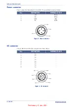
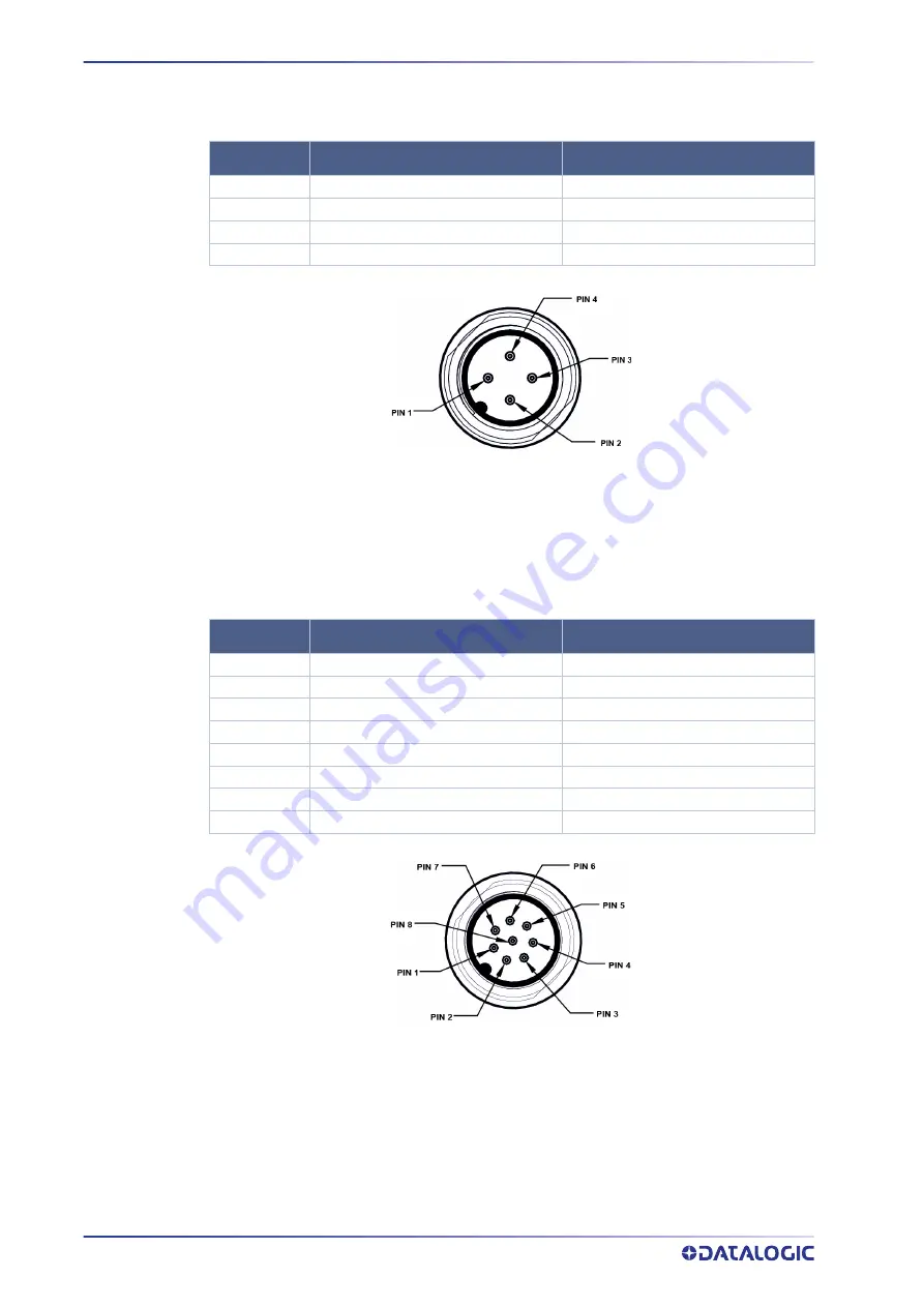
Power connector
Power supply interface adapts 12 to 32VDC. The pin definitions are as follows:
1
+Vcc
Brown
2
Q2
White
3
GND
Blue
4
Q1
Black
Figure 5 - Power connector
I/O connector
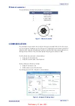
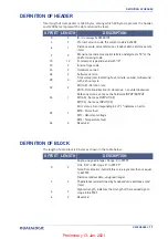
The pin definitions of the I/O connector are shown below:
1
n.c.
-
2
n.c.
-
3
n.c.
-
4
n.c.
-
5
n.c.
-
6
n.c.
-
7
n.c.
-
8
n.c.
-
Figure 6 - I/O connector
No.
DEFINITION
WIRING COLOR
No.
DEFINITION
WIRING COLOR
Preliminary 13-Jan-2021
Summary of Contents for LGS-N50
Page 1: ...LGS N50 USER MANUAL Navigation LiDAR Preliminary 13 Jan 2021 ...
Page 26: ...22 LGS N50 APPENDIX A DATA PACKET Preliminary 13 Jan 2021 ...
Page 27: ...USER MANUAL 23 APPENDIX B MECHANICAL DIMENSIONS Preliminary 13 Jan 2021 ...
Page 28: ...MECHANICAL DIMENSIONS 24 LGS N50 Preliminary 13 Jan 2021 ...
Page 29: ...USER MANUAL 25 APPENDIX C EXAMPLE OF ELECTRICAL CONNECTION OUTPUT Q1 Preliminary 13 Jan 2021 ...
Page 30: ...Preliminary 13 Jan 2021 ...
Page 31: ...Preliminary 13 Jan 2021 ...


