
Connections
USB Client Connection
Connect the Single Slot Dock to the host by means of a Micro-B USB
cord, such as Datalogic 94A051968 cable.
Once the host has been turned on, insert the Lynx into the dock.
A.
Host computer
B.
94A051968 Micro-B to Std-A USB straight cable
C.
94A150036 Lynx Single Slot Dock
D.
Power Adapter
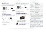
Connection to USB Peripherals
Connect the Single Slot Dock to the peripheral by means of a Micro-A
USB cord, or use a Micro-A to Std-A receptacle USB adapter such as
Datalogic 94A051969 (together with a standard USB cable if needed).
A.
USB Peripheral (memory)
B.
Standard A to Micro A USB Cable
C.
94A051969 Micro-A to Std-A receptacle USB adapter
D.
94A150036 Lynx Single Slot Dock
E.
Power Adapter
RS232 Connection
Connect the Single Slot Dock to the host by means of a standard null
modem cable such as Datalogic 94A051020 CAB-427 for 9-pin
connections.
Once the host has been turned on, insert the Lynx into the dock.
A.
Host computer
B.
94A051020 9-pin serial cable
C.
94A150036 Lynx Single Slot Dock
D.
Power Adapter
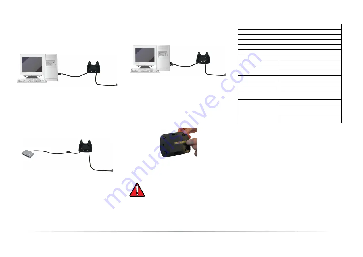
Communication Module Extensions
To install a communication module, remove the label covering the
communication module connector on the bottom of the dock, as
shown in the figure below:
The communication modules available are the following:
•
94ACC1371 Single Slot Dock Ethernet Module
•
94ACC1372 Single Slot Dock Modem Module.
Technical Specifications
FCC Compliance
This equipment has been tested and found to comply with the limits
for a Class A digital device, pursuant to part 15 of the FCC Rules. These
limits are designed to provide reasonable protection against harmful
interference when the equipment is operated in a commercial
environment. This equipment generates, uses, and can radiate radio
frequency energy and, if not installed and used in accordance with the
instruction manual, may cause harmful interference to radio
communications. Operation of this equipment in a residential area is
likely to cause harmful interference in which case the user will be
required to correct the interference at his own expense.
Modifications or changes to this equipment without the expressed
written approval of Datalogic could void the authority to use the
equipment. This device complies with PART 15 of the FCC Rules.
Operation is subject to the following two conditions: (1) This device
may not cause harmful interference, and (2) this device must accept
any interference received, including interference which may cause
undesired operation.
D
A
B
C
C
E
A
B
D
WARNING
Do not use the cradle in a PoE network, i.e. in a
network with PSE able to supply power: there is the
risk to compromise, in irreversible way, the
functionality of the Ethernet Module.
D
A
B
C
Electrical Features
Power supply
1
1.
This device is intended to be connected to a UL Listed/CSA Certified Power
Unit marked “Class 2” or LPS power source rated 5 V, 3A. The package may
include international plug adapters. The adapters must be plugged in the
power supply before the power supply itself is plugged on the wall outlet.
5 VDC ± 5% @ 3A
Consumption
Max 3 A with PDA inserted
Spare slot charge time
Std Battery
3h
High Cap Battery
4h 30
Communication Features
Interface
RS232, USB 1.1 version
Baud Rate
RS232 = 9600 - 115200
Environmental Features
Working Temperature
2
2.
When inserted in the spare slot, batteries must be charged at a tempera-
ture ranging from 0° to 44°C. Never charge the main device or spare bat-
teries in a closed space where excessive heat can build up.
0° to +50°C / 32° to 122°F
Storage Temperature
-20° to +70°C / -4° to 158°F
Humidity
95% without condensation
Electrostatic discharge
EN 61000-4-2
4 KV contact / 8 KV air
Physical Features
Dimensions
110 x 140 x 72 mm / 4.3 x 5.5 x 2.8 in
Weight (without cables)
185 g / 6.5 oz
Indicators
Green power-on LED
Bicolored battery charge status LED


