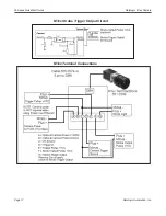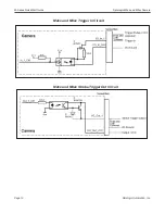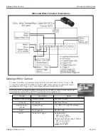
MX80 Processor Power Supply Connection
M-Series QuickStart Guide
Datalogic Automation, Inc.
Page 8
MX80 Processor Power Supply Connection
The MX80 power input uses a Datalogic-supplied
connector. Wire the power supply cable to the con-
nector, then plug it into the power connector on the
rear of the processor. The ground terminal on the
power input must be connected to the power supply’s
grounded chassis/enclosure. This connection is
needed to insure electromagnetic compliance and
proper operation.
The MX80 processor requires approximately 5A @
24VDC. Datalogic recommends using a 24 VDC
power supply capable of providing 5A current. This
voltage is commonly used in many manufacturing
environments.
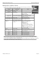
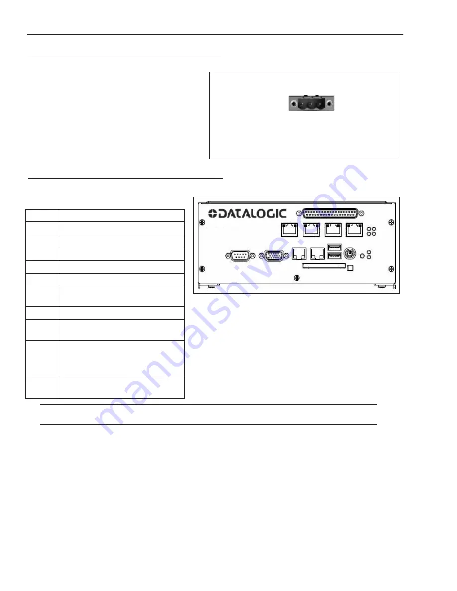
MX20 and MX40 Front Panel Connections
This is the MX20 and MX40 Processor’s front
panel.
Note
: If a Compact Flash card is present in the socket, it can be used for extended storage by the MX20 and MX40 pro-
cessors. Do NOT insert or remove the card while the unit is powered on.
Symbol
Function
A
B
Reset Button (Resets the processor)
C
Keyboard and Mouse
D
USB Ports 2.0 (2)
E
LAN Ethernet Ports (2)
F
Compact Flash Socket (See Note
below)
G
VGA Connector
H
Serial Port 1 - See “MX20 and MX40
Serial Cable” on page 1-11
I
M-Series Camera Connectors (CAM1-
CAM4) MX20 has only 2 POE ports
(CAM1-CAM2)
Cable 606-0457-x
J
Digital I/O Connector - Cable 606-
0675-xx with terminal block 661-0403
Connect V+ terminal to Power Supply 10 to 30VDC*
Connect V- terminal to Power Supply Minus
Connect GND terminal to Power Supply Circuit Ground
GND
V-
V+
Power Connecto
r
POWER INPUT
10-30VDC
C
B A
D
E
F
G
H
I
J
A


