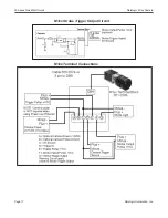
MX80 Serial Cable
M-Series QuickStart Guide
Datalogic Automation, Inc.
Page 12
MX80 Serial Cable
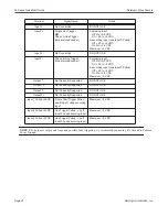
The MX80 processor provides four serial port connections. The connector on the front panel is Serial Port 1 (COM 5)
which uses a standard serial cable. CAM 1 controls this serial port.
The rear panel connector has three serial port connections for Serial Ports 2, 3, and 4 (COM 2, 3, and 4 respectively).
CAM 2 controls Serial Port 2, CAM 3 controls Serial Port 3, and CAM 4 controls Serial Port 4. Use the Datalogic pro-
vided cable which has a DB-62P connector on one end and three standard serial port connectors (DB9) on the other end.
The connector wiring pin numbers on the three DB9 connectors are the same as the MX20 and MX40.
M-Series Processor I/O Wiring
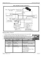
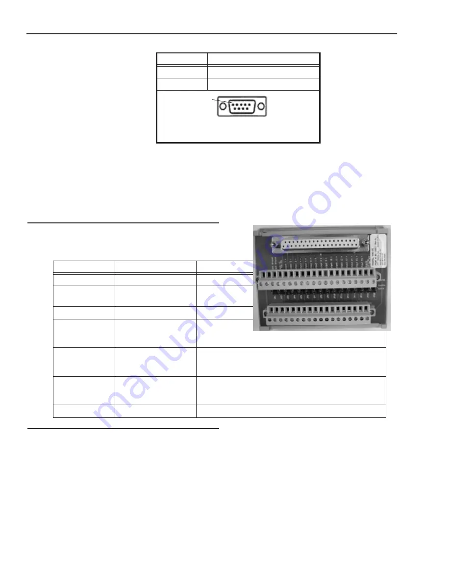
To connect Processor power and input/output signals, use cable
606-0675-xx (37 pin D-sub Male to Male) with terminal block
661-0403.
Input Characteristics
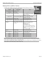
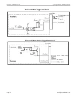
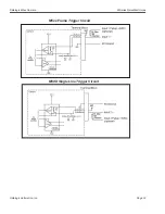
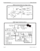
The diagrams and table below describe the input characteristics and how to wire a sensor to a general purpose or event
input.
8
Clear To Send (CTS)
9
Ring Indicator (RI)
9 Pin Male
(Pin Side)
Terminal Name
Signal
Notes
Input Cmn (2)
Input Common
Input 1 through
Input 16
Input 1+ through
Input 16+
See Input table
on page 1-13
Output Ground (2)
Output Ground
5 to +35
VCC
Output Control Voltage
See Supply
Voltage table
on page 1-13
Output 1 through
Output 16
Outputs 1 through 16
(sinking or sourcing
selectable)
See “Pullup Jumpers to Enable Sourcing” on page 1-14
Outputs Sourcing
Pullups VCC
Output Pullup - use if
Output needs to be
sourcing
+24 VDC
(Jumpers JP1 through JP16 enable/disable connection)
JP1 through JP16
Pullup Enable/Disable
See “Pullup Jumpers to Enable Sourcing” on page 1-14
Pin Number
Signal Name
Pin 1


