M-Series QuickStart Guide
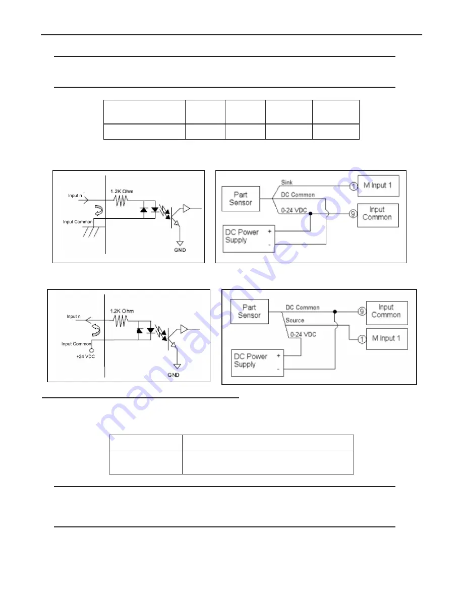
General Purpose Input Circuit (Sinking)
Page 13
Datalogic Automation, Inc.
Note
: All connections to inputs must be made using properly grounded shielded cable.
All inputs must be wired as either sinking or sourcing, they cannot be mixed. There is only one “Input Common” connec-
tion for all the inputs.
General Purpose Input Circuit (Sinking)
General Purpose Input Circuit (Sourcing)
Output Characteristics
The M-Series Processors contain sixteen general-purpose output connections.
NOTES
: An external power source is required to power an output load. The outputs are merely switches that are open or
closed. All output connections must use properly grounded and shielded cable.
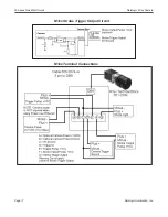
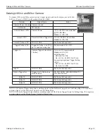
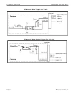
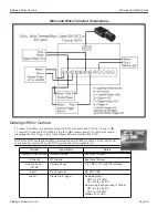
The Trigger Signal and Strobe Output for M-Series cameras are separate and not part of the M-Series Processor inputs and
outputs. See M-Series Cameras on page 3-1 for details.
Input Resistance
(nominal)
Input
Voltage
Turn On
Voltage
Turn Off
Voltage
Isolated
Voltage
1.2k @ 0.5 W
0-24 Vdc
>3 Vdc
< 0.8 Vdc
2500 Vrms
Supply Voltage
+5 VDC (minimum) to +35 VDC (maximum)
Sink Current
(maximum)
1 Amp per output


