


M-Series QuickStart Guide
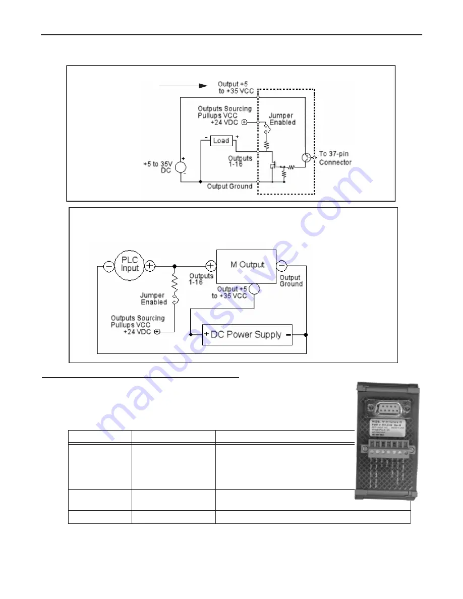
General Purpose Output Circuit (Sourcing)
Page 15
Datalogic Automation, Inc.
General Purpose Output Circuit (Sourcing)
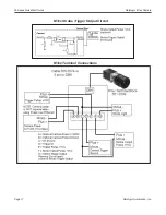
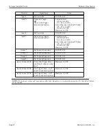
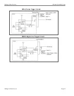
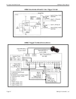
Camera Trigger, Power, and Strobe Wiring
Datalogic M1xx Camera
To connect M1xx camera power, trigger signals, and strobe outputs, use cable 606-0674-xx (6
pin to DB9) with terminal block 661-0399.
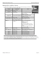
Terminal Name
Signal
Notes
Optional Camera
Power +12VDC
Camera Power
Required when NOT using Power
Over Ethernet (PoE)
+12 VDC (+-10%) @ 250 mA Max
Maximum: +13.2 VDC
Minimum: +11.3 VDC
Optional Camera
Power Ground
Camera Power Ground
Required when NOT using Power
Over Ethernet (PoE)
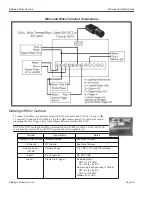
I/O Ground
I/O Ground
This is not an output voltage source. An
external power source must be con-
nected to VCC, as indicated.
5 to +35 VCC is not
an output voltage source. An
external power source must
be connected as indicated.
Note: To turn PLC On, turn
M Output Off. To turn PLC
Off, turn M Output On.


