


M-Series QuickStart Guide
Flat Surface Mounting
Page 5
Datalogic Automation, Inc.
Flat Surface Mounting
The M-Series Processor may be mounted on any stable surface using the provided case mounting brackets. (Use the
appropriate bracket for the Processor model.) Allow at least 1.5 inches (38.1 mm) of clearance at the sides and top of the
unit.
DIN Rail Mounting
The M-Series Processor may be bottom-mounted on a DIN rail using the optional DIN Rail Mount kit (MX20/MX40: Part
# 606-0683; MX80: Part # 95A906038).
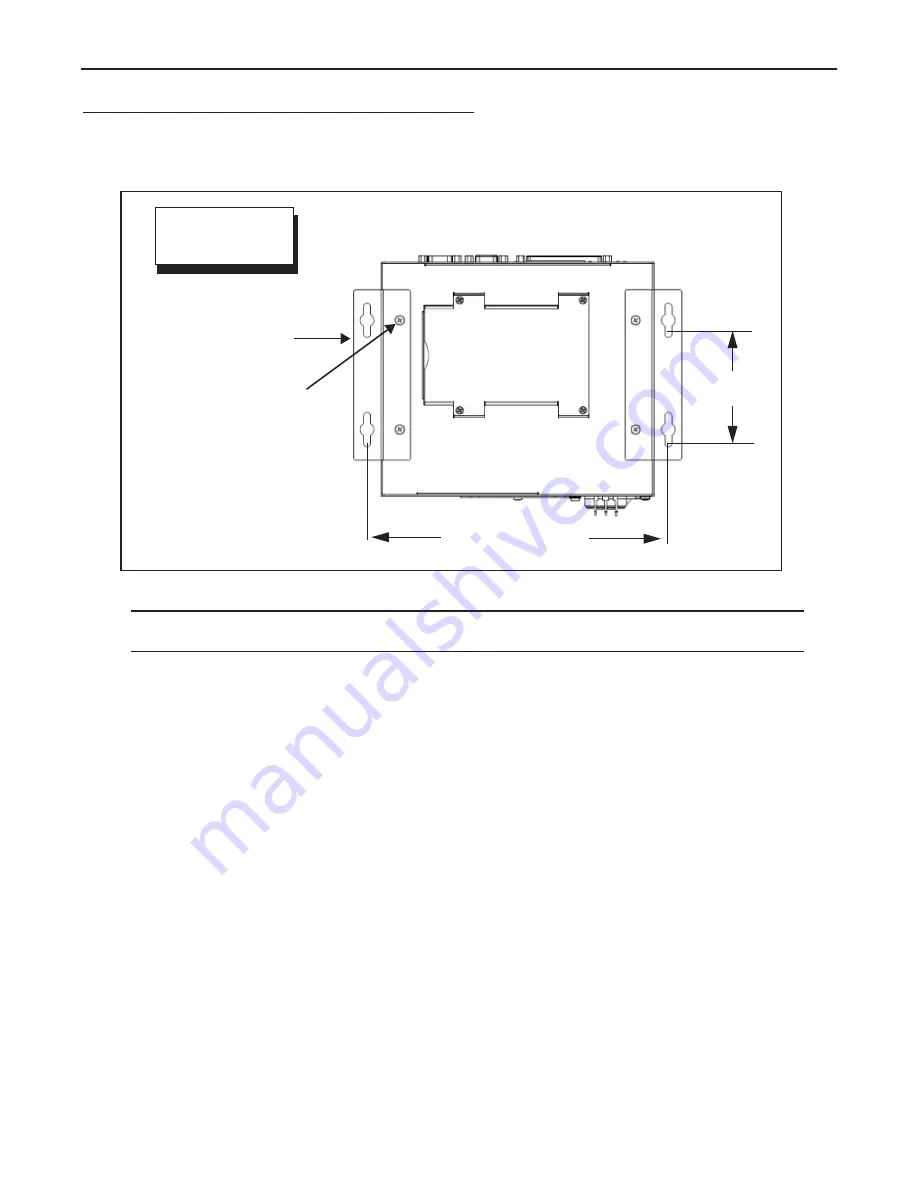
UNITS: inch [mm.]
Bottom View
Mounting Hole
Dimensions
Mounting Brackets (x2)
Provided
Bracket Mounting Screws (x4)
M4, 0.7 mm pitch, 5 mm length -
Provided
MX20; MX40=8.7 [221]
MX80 =9.92 [252]
All models
3.2 [80.0]
Mounting Bracket Installation
NOTE: If the Processor uses a Compact Flash card, mount with the Processor front facing upward so the CF
card does not fall out due to vibration.
To mount the Processor using the mounting brackets:
1.
Fasten the two mounting brackets to the bottom of the Processor using the bracket mounting screws.
2.
Using the mounting brackets as a template, mark the surface mounting holes in the desired location. The sur-
face must be sufficiently sturdy to hold the unit, stable, and free of vibration.
3.
Drill four surface mounting holes in the mounting surface.
4.
Insert four mounting screws in the mounting holes and tighten them until approximately 0.2 inches (5 mm) is
left exposed. The mounting screws must be at least size #12 (min. 0.216 inches or 5.486 mm) and long
enough to provide sufficient support.
5.
Maneuver the Processor so mounting bracket slots align with the mounting screws.
6.
Place the slots over the screws and slide the Processor down until the screws fit snugly into the mounting
bracket slots.
Processor front
Flat Surface Mounting
(Front Up)
IMPORTANT: See Mounting Warning on Page 1


