Product Reference Guide
2-29
Figure 2-16. Model 8300RD Physical Measurements
1
8
.5mm
2
8
.4mm
D
ua
l Di
s
pl
a
y
S
ingle Di
s
pl
a
y
3
29mm
3
25mm
292.5mm
227.5mm
116.
3
9mm
112mm
60mm
264mm
116.
3
9mm
112mm
60mm
25.5mm
8
5.1mm
41.99mm
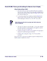
5. Feed the entire length of the Remote Scale Display interface cable
through the cable routing hole so that the assembled Remote Scale
Display can be positioned over the mounting screw holes.
6. If present, remove the rubber band from the connector end.
7. Install mounting screws or bolts to complete the installation of the
Remote Scale Display. Take care not to pinch or pierce the interface
cable while securing the Remote Scale Display to the checkstand.
Summary of Contents for Magellan 8500Xt
Page 1: ...MagellanTM 8500Xt Product Reference Guide...
Page 14: ...12 MagellanTM 8500Xt Scanner NOTES...
Page 70: ...2 40 MagellanTM 8500Xt Scanner NOTES...
Page 88: ...3 18 MagellanTM 8500Xt Scanner Figure 3 6 Removing Replacing the Gasketed DLC Window a b c d...
Page 93: ...Product Reference Guide 4 5 Figure 4 1 7 Segment LED Display 7 Segment Display Models vary...
Page 102: ...4 14 MagellanTM 8500Xt Scanner NOTES...
Page 138: ...6 20 MagellanTM 8500Xt Scanner NOTES...
Page 416: ...7 278 MagellanTM 8500Xt Scanner NOTES...
Page 428: ...A 12 MagellanTM 8500Xt Scanner...
Page 448: ...D 2 MagellanTM 8500Xt Scanner NOTES...
Page 462: ...E 14 MagellanTM 8500Xt Scanner NOTES...
Page 477: ...Product Reference Guide F 15 NOTES...


