Installation Overview
Product Reference Guide
2-21
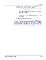
When power is applied to the unit, the normal indicator sequence is:
•
The scanner indicator (top-most, green LED) will be lit (dim)
steadily.
•
The EAS indicator (bottom-most, tri-color LED) will flash ON/
OFF during power-up. Additionally, the 7-segment display will
flash the number ‘9’. indicating the EAS system is being initialized.
•
If the Selftest detects a problem, the 7-segment display will display a
number code. Refer to
Chapter 4
,
Problem Isolation
, for a descrip-
tion of failure codes and problem isolation procedures.
4. The unit should be permitted to reach thermal equilibrium before
proceeding to the next steps. (Reference the topic
Warm-Up Time
in
Chapter 1
.) When the unit is moved from a cooler temperature
(such as a storage area) to a warmer environment (such as a check-
stand location), a period of 60 minutes must be allowed to acclimate
the unit to ambient conditions. Once installed and powered up, a
“power-up” warm-up period of 15 minutes must be allowed before
calibrating or performing weighing operations. These two warm-
up periods may run concurrently.
5. Verify that the scanner or scanner/scale passes an operational test by
observing the following:
NOTE
Scale calibration may be necessary to obtain a zero reading on the display on
rare occasions.
Summary of Contents for Magellan 9500?
Page 1: ...Magellan 9500 9500 9504 9504 with SmartSentry Product Reference Guide...
Page 28: ...1 16 Magellan 9500 NOTES...
Page 100: ...4 14 Magellan 9500 NOTES...
Page 116: ...5 16 Magellan 9500 NOTES...
Page 396: ...6 280 Magellan 9500 NOTES...
Page 416: ...B 10 Magellan 9500 NOTES...
Page 426: ...D 2 Magellan 9500 NOTES...
Page 442: ...E 16 Magellan 9500 NOTES...
Page 458: ...F 16 Magellan 9500 NOTES...


