Site Preparation and Installation
36
Magellan™ 9800i Scanner
Operational Verification
Follow these steps to ensure that your unit has arrived undamaged and is fully functional before
installing it in the counter and connecting it to your POS system.
1. If the unit is a scanning-scale, connect the Remote Scale Display to the proper connector
on the unit’s connector panel (refer to
NOTE
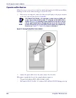
if the Remote Scale Display is not connected, a scanner power-up Selftest will
sound a long, low beep, and the number “8” will appear on the Health & Status
Indicator (see
) indicating a remote display error. Power-down, connect
a known-good Remote Display to the appropriate port, and restart to correct this
problem. Alternatively, you can disable the Remote Display using programming
bar codes (see
, for more information).
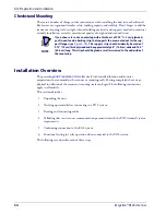
Figure 24. Viewing the Health & Status Indicator
2. Connect the power cable, first at the scanner, then at the AC outlet.
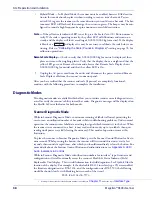
When power is applied to the unit, the normal indicator sequence is:
•
The good read indicator LEDs will be lit (dim) steadily.
•
[EAS models ONLY] The EAS
indicator LED will flash ON/OFF during power-up.
Summary of Contents for Magellan 9800i
Page 1: ...MagellanTM 9800i Product Reference Guide...
Page 62: ...Site Preparation and Installation 50 Magellan 9800i Scanner NOTES...
Page 102: ...Calibration Procedures 90 Magellan 9800i Scanner NOTES...
Page 112: ...Programming 100 Magellan 9800i Scanner NOTES...
Page 158: ...Enter Exit Programming Mode 146 Magellan 9800i Scanner NOTES...
Page 174: ...EAS Features 162 Magellan 9800i Scanner NOTES...
Page 378: ...Enter Exit Programming Mode 366 Magellan 9800i Scanner NOTES...
Page 400: ...2D Symbology Programming 388 Magellan 9800i Scanner NOTES...
Page 414: ...402 Magellan 9800i Scanner NOTES...
Page 424: ...412 Magellan 9800i Scanner NOTES...
Page 438: ...426 Magellan 9800i Scanner NOTES...
Page 450: ...438 Magellan 9800i Scanner NOTES...


