Product Reference Guide
37
•
Additionally, the Health & Status Indicator will flash the number ‘9’, indicating the EAS
system is being initialized.
CAUTION
NOTE
On rare occasions, performance of scale calibration may be necessary to obtain a
zero reading on the display.
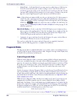
If the Selftest detects a problem, the Health & Status Indicator will display a num-
ber code. Refer to
, for a description of failure
codes and problem isolation procedures.
3. The unit should be permitted to reach thermal equilibrium before proceeding to the next
steps. (Reference the topic
in
.) When the unit is moved from
a cooler temperature (such as a storage area) to a warmer environment (such as a check-
stand location), a period of 60 minutes must be allowed to acclimate the unit to ambient
conditions. Once installed and powered up, a “power-up” warm-up period of 15 minutes
must be allowed before calibrating or performing weighing operations. These two warm-
up periods may run concurrently.
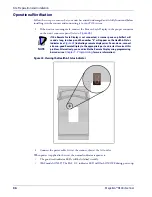
4. Verify that the scanner or scanning-scale passes an operational test by observing the fol-
lowing:
Scanner —
Pass UPC/EAN bar code labels in front of the scanner’s windows. Since the interface
cable is not yet connected to the POS terminal, the scanner may be limited to reading
only one or two labels (see the note that follows). The scanner indicates when each label
has been successfully read by flashing the green scanner light and emitting a good read
tone (beep).
NOTE
When not connected to the host, the scanner may be limited to reading only one
or two labels. (This limitation is dependent upon the interface type.) To scan mul-
tiple labels without connecting to the host, place the unit in Scanner Diagnostic
Mode by pressing the Scanner Control Button for four seconds.
EAS System —
The way in which EAS tags are deactivated is dependent upon the way the scan-
ner is currently programmed with regard to EAS Mode. (See “EAS Mode” on page 42.) To
test EAS system function...
•
Coupled Mode — Pass an item containing both a bar code and an active EAS tag over the
scanner. Successful deactivation is indicated by the bottom-most LED flashing first red,
then orange, then returning to green. The beeper will sound a good read beep.
If you have enabled the manual deactivation function available for Coupled Mode (see
“Manual EAS Deactivation Push Button” on page -48), test the function by pressing the
bottom push button. A ticking sound will be heard which should cease upon deactivating
an EAS tag.
•
Decoupled Mode — In this mode, items do not require a bar code to be scanned to arm
the deactivation function. Simply pass an active EAS tag over the scanner in the same
direction you would scan a bar code. The bottom-most LED will flash red to indicate
deactivation. No beep is sounded to indicate deactivation in this mode.
Summary of Contents for Magellan 9800i
Page 1: ...MagellanTM 9800i Product Reference Guide...
Page 62: ...Site Preparation and Installation 50 Magellan 9800i Scanner NOTES...
Page 102: ...Calibration Procedures 90 Magellan 9800i Scanner NOTES...
Page 112: ...Programming 100 Magellan 9800i Scanner NOTES...
Page 158: ...Enter Exit Programming Mode 146 Magellan 9800i Scanner NOTES...
Page 174: ...EAS Features 162 Magellan 9800i Scanner NOTES...
Page 378: ...Enter Exit Programming Mode 366 Magellan 9800i Scanner NOTES...
Page 400: ...2D Symbology Programming 388 Magellan 9800i Scanner NOTES...
Page 414: ...402 Magellan 9800i Scanner NOTES...
Page 424: ...412 Magellan 9800i Scanner NOTES...
Page 438: ...426 Magellan 9800i Scanner NOTES...
Page 450: ...438 Magellan 9800i Scanner NOTES...


