INSTALLATION
37
3
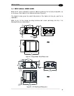
3.2 MECHANICAL DIMENSIONS
Matrix
210™ can be installed to operate in different positions. The four screw holes (M3 x 4)
on the body of the reader are for mechanical fixture (Figure 27).
The diagram below gives the overall dimensions of the reader and may be used for its
installation.
Refer to par. 3.3 for various mounting solutions and correct positioning and chp. 7 for
Reading Distance considerations.
32
[1.25
]
9.0
[0.36]
25.0
[0.98]
7
[0.29]
M3X4
n°4
25
[0.9
8
]
45
[1.7
6
]
54
[2.13]
11
[0.4
5
]
Figure 27
– Straight Model Overall Dimensions
45
[1.76]
10.0
[0.39
]
25.0
[0.98]
11.0
[0.43
]
25
[0.9
8]
50
[1.97]
7
[0.29]
6
[0.25]
Figure 28
– 90° Model Overall Dimensions
mm
[in]
mm
[in]
Optical axis
Optical axis
Summary of Contents for Matrix 210
Page 1: ...MATRIX 210 Reference Manual...
Page 142: ...www datalogic com...

