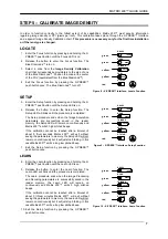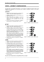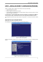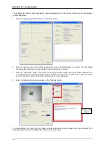
background image


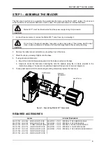
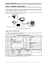
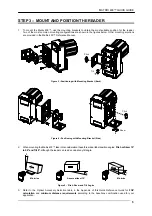
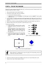
MATRIX 400™ QUICK GUIDE 

15


OPTICAL ACCESSORY SELECTION 

 
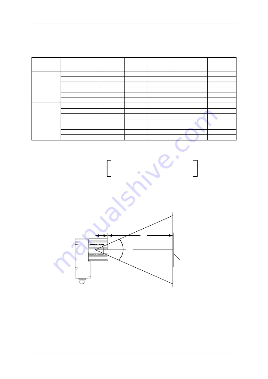
Refering to Figure 18 and the formula below, use the data in the following table to calculate the FOV for your 
application. 
 

Model Lens 

Viewing Angle 

Horizontal


Viewing 

Angle 

Vertical


Viewing 

Angle 

Diagonal


Min Focus Distance


mm 

Lighting System

LNS-1109 9mm 

48.5° 

39.5° 

60° 

85 

LT-002 

LNS-1112 12.5mm 

37° 

30° 

46.5° 

85 

LT-002 

LNS-1116 16mm 

28.5° 

23° 

36° 

85 

LT-001 

LNS-1125 25mm 

18.5° 

15° 

23.5° 

135 

LT-001 

LNS-1135 35mm 

13° 

10,5° 

16.5° 

235 

LT-006 

400-400-0x0 

(SXGA) 

LNS-1150 50mm 

9° 

7° 

11.5° 

500 

LT-006 

LNS-1006 6mm 

59.5° 

46.5° 

71° 

85 

LT-002 

LNS-1109 9mm 

40.5° 

31° 

49.5° 

85 

LT-002 

LNS-1112 12,5mm 

31° 

23.5° 

38° 

85 

LT-002 

LNS-1116 16mm 

24° 

18° 

30° 

85 

LT-001 

LNS-1125 25mm 

15° 

11.5° 

19° 

135 

LT-001 

LNS-1135 35mm 

11° 

8.5° 

13.5° 

235 

LT-006 

400-600-0x0 

(UXGA) 

LNS-1150 50mm 

7.5° 

5.5° 

9.5° 

500 

LT-006 

 
The viewing angle has a tolerance of 

±

 1° depending on the focus distance. 


FOV

x

 = 2  (d + 35 mm) tan (

α

x

/2) 


where: 

FOV

x

 = horizontal, vertical or diagonal FOV


α

x

 = horizontal, vertical or diagonal viewing angles. 

d

 = focus distance 


d

35 mm 

FOV 

plane 

α


Figure 18 – Reading Distance References 


Example: 

 
The FOV for a 

Matrix 400-600-0x0 base

 using the 

16 mm lens

 at a 

focus distance of 200 mm

 is: 


FOV

H

 = 2 [(200 mm + 35 mm) tan (24°/2)] = 

100 mm


FOV

V

 = 2 [(200 mm + 35 mm) tan (18°/2)] = 

74 mm


Summary of Contents for Matrix 400

Page 1: ...al Illuminator separate accessory Ethernet Connection LED Ethernet Models Only 11 NOTE This manual illustrates a Stand Alone application For other types of installations such as Pass Through Multiplex...

Page 2: ...com E En Internet est n disponibles las versiones actualizadas de los drivers y documentaci n de este producto Direcci n Internet www automation datalogic com SERVICES AND SUPPORT Datalogic provides...

Page 3: ...4 internal illuminator spacers into the holes provided on the base b Align and mount the Illuminator board tightly onto the spacers using the 4 screws provided in the illuminator package The spacers a...

Page 4: ...inout when the Matrix 400 reader is connected by means of the C BOX 100 C BOX 100 Terminal Block Connectors Power Outputs 1 3 5 VS 21 OUT 1 2 4 6 GND 22 OUT 1 7 8 EARTH GROUND 23 OUT 2 20 40 Reserved...

Page 5: ...cket Back Figure 4 Positioning with Mounting Bracket Side 2 When mounting the Matrix 400 take into consideration these three ideal label position angles Pitch or Skew 10 to 20 and Tilt 0 although the...

Page 6: ...ction The Blue Diamonds turn on The procedure is as follows a Adjust the Focus ring towards the Near position until the Blue Diamonds are perfectly in focus see Figure 7 At long focal distances a skew...

Page 7: ...ion parameters are successfully saved in the reader memory the Setup LED will remain on continuously and Matrix 400 emits 3 high pitched beeps If the calibration cannot be reached after a timeout of a...

Page 8: ...igh pitched beeps If the calibration cannot be reached after a timeout of about 5 five seconds Matrix 400 will exit without saving the parameters to memory the Setup LED will not remain on continuousl...

Page 9: ...l VisiSet turn on the PC that will be used for the configuration running Windows 98 2000 NT or XP then insert the VisiSet CD ROM wait for the CD to autorun and follow the installation procedure This c...

Page 10: ...s Quick Reference Guide 3 Press the Positioning button The reader continuously acquires images and gives visual feedback in the view image window to indicate when the code is centered with respect to...

Page 11: ...sult section of the Autolearning Wizard window shows the parameter settings and the code type results 6 Select a Saving Options choice and press the Save button 7 Close the AutoLearning Wizard NOTE If...

Page 12: ...ion Once entered the Bar Graph on the five LEDs is activated and if the reader starts reading codes the Bar Graph shows the Good Read Rate In case of no read condition only the STATUS LED is on and bl...

Page 13: ...rameter Setup window in off line mode Advanced configuration is addressed to expert users being able to complete a detailed reader configuration The desired parameters can be defined in the various fo...

Page 14: ...ng unknown codes In normal operating mode the colors and meaning of the five LEDs are illustrated in the following table READY green This LED indicates the device is ready to operate GOOD green This L...

Page 15: ...5 500 LT 006 LNS 1006 6mm 59 5 46 5 71 85 LT 002 LNS 1109 9mm 40 5 31 49 5 85 LT 002 LNS 1112 12 5mm 31 23 5 38 85 LT 002 LNS 1116 16mm 24 18 30 85 LT 001 LNS 1125 25mm 15 11 5 19 135 LT 001 LNS 1135...

Page 16: ...Post Royal Mail 4 State Customer Code 39 Standard and Full ASCII Interleaved 2 of 5 QR Code Standard and Direct Marking Kix Code Japan Post Codabar MAXICODE PLANET Code 93 Aztec Code POSTNET POSTNET...

Page 17: ...40 Figure 19 Matrix 400 Overall Dimensions 4 0 16 M4 0 16 N 5 4 3 0 17 50 1 97 61 2 40 72 5 2 85 83 5 3 29 12 5 0 49 12 5 0 49 12 5 0 49 12 5 0 49 40 1 57 3 0 12 50 1 97 70 2 76 4 2 0 17 8 5 0 3 3 4...

Page 18: ...ted 10 to 30 V minimum 1 A CE COMPLIANCE Warning This is a Class A product In a domestic environment this product may cause radio interference in which case the user may be required to take adequate m...

Page 19: ...Lieferanten ber den sie das Produkt erworben haben oder besuchen sie unsere Hompage unter www automation datalogic com FRAN AIS Information aux utilisateurs concernant la Directive Europ enne 2002 96...

Page 20: ...MATRIX 400 QUICK GUIDE 20 SERIAL NUMBER REFERENCES Place the replicate Matrix 400 base lens and illuminator serial number labels here for reference Serial Numbers Matrix 400 Lens Illuminator 821001350...

Reviews: