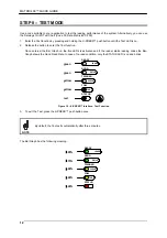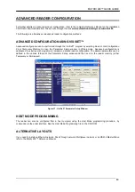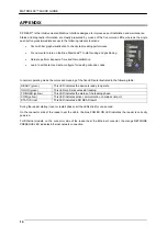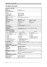
MATRIX 400™ QUICK GUIDE
5
STEP 3 – MOUNT AND POSITION THE READER
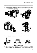
1. To mount the Matrix 400™, use the mounting brackets to obtain the most suitable position for the reader.
Two of the most common mounting configurations are shown in the figures below. Other mounting solutions
are provided in the Matrix 400™ Reference Manual.
Figure 3 –Positioning with Mounting Bracket (Back)
Figure 4 –Positioning with Mounting Bracket (Side)
2. When mounting the Matrix 400™ take into consideration these three ideal label position angles:
Pitch or Skew 10°
to 20° and Tilt 0°
, although the reader can read a code at any tilt angle.
P
S
T
Minimize
Assure at least 10°
Minimize
Figure 5 – Pitch, Skew and Tilt Angles
3. Refer to the Optical Accessory Selection table in the Appendix of this Quick Reference Guide for
FOV
calculation
and
minimum distance requirements
according to the base/lens combination used for your
application.
Tilt
Skew
Pitch
Pitch


