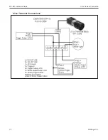
U1xx Camera Connection (Alternate)
MX-U81 Hardware Guide
Datalogic S.r.l.
3-12
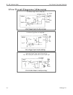
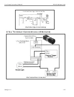
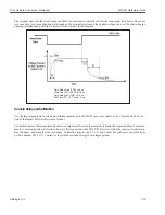
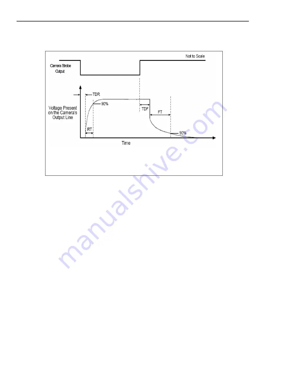
The response times for the strobe output on the U1xx camera will typically fall into the ranges specified below. The exact
response time for your application will depend on the external resistor and the applied voltage you use.The shutter begins
opening simultaneously with the “Camera Strobe Output” in the diagram.
Camera Setup and Calibration
Use the Impact programs to setup and calibrate cameras with a MX-U81 processor. (Refer to the Camera Setup Tab sec-
tion of the Impact Software Reference Guide.)
Calibration insures that measurements shown in Impact software tools accurately indicate the inspected object's measure-
ments. A camera requires calibration when it is first connected to the MX-U81 Processor, when the camera-to-subject dis-
tance changes, and when the lens is changed. Calibration targets with 0.5, 1.0, and 2.0 mm dot pitches are available from
us (Part number 381-1177). Contact us for printed versions of targets with larger pitches.
Time Delay Rise (TDR) = 40 us
Rise Time (RT) = 20 us to 70 us
Time Delay Fall (TDF) = 0.6 us
Fall Time (FT) = 0.7 us to 1.4 us
Summary of Contents for MX-U81
Page 1: ...MX U81 Hardware Guide for Processor and Cameras Revision Date October 26 2017 ...
Page 4: ......
Page 26: ...Battery MX U81 Hardware Guide Datalogic S r l 2 10 ...
Page 33: ...MX U81 Hardware Guide U1xx Camera Connection 3 7 Datalogic S r l U1xx Terminal Connections ...
Page 52: ...JAI Camera MX U81 Hardware Guide Datalogic S r l 3 26 ...
Page 64: ...U1xx MX U81 Hardware Guide Datalogic S r l 5 4 ...

