6
P-SERIES™
CHAPTER 2
RAPID CONFIGURATION
STEP 1- CONNECT THE SYSTEM
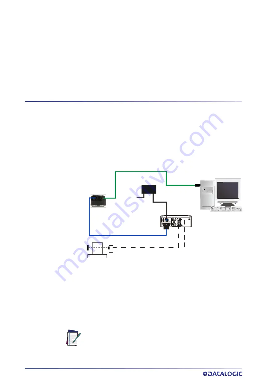
In the typical layout shown in the figure below, an Ethernet host is connected to the
camera. The camera can use an external trigger or internal software trigger to signal
image acquisition. If an external trigger is used, the Ethernet host connection is needed
only for camera and program configuration and inspection monitoring.
The CBX is used to facilitate the connection between the camera, external trigger, and
optional input and output devices.
Figure 1- P-Series™ ™ Stand Alone Layout to Ethernet Host
• Power Supply Connection
Use the PG600x AC/DC Power Supply Unit (3 versions for European, UK or US
plug).
• CBX Connection
Use CAB-DSxx-S between the P-Series™ camera and the CBX for power, external
trigger device (photocell), and additional I/O connections.
Use the CAB-ETH-Mxx for the Ethernet connection to the host.
NOTE
The P-Series™ does not support sourcing power towards the CBX in order
to power I/O devices. These devices must be powered through the CBX or
from an external source.
Camera
CAB-DSxx
PG-600x
CAB-ETH-Mxx
CBX500
or CBX800
I/O
Ext. Trigger


