Plug and Play
Product Reference Guide
1-5
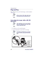
3. Plug the serial connector into the serial port on your computer.
Tighten the two screws to secure the connector to the port.
4. If the terminal does not support Power Off the Terminal (P.O.T.)
connections plug the power supply into the host connector and the
AC outlet.
5. Once the imager has been fully connected, power up the com-
puter.
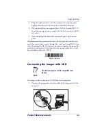
All communication parameters between the imager and terminal must
match for correct data transfer through the serial port using RS-232 pro-
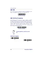
tocol. Scanning the RS-232 interface bar code, programs the imager for
an RS-232 interface at 115,200 baud, parity–none, 8 data bits, 1 stop
bit, and adds a suffix of a CR LF.
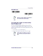
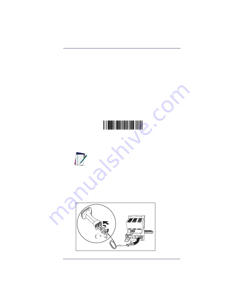
Connecting the imager with USB
An imager can be connected to the USB port of a computer.
1. Connect the appropriate interface cable to the imager and to the
computer.
NOTE
This interface applies to USB compatible mod-
els only.
RS-232 Interface
U S
B
Captive
Screws
Retainer Boss
Cable Connector
Summary of Contents for POWERSCAN 7000 2D Imager
Page 1: ...PowerScan 7000 2D Imager Product Reference Guide...
Page 8: ...vi PowerScan 7000 2D...
Page 30: ...Terminal Interfaces 2 12 PowerScan 7000 2D NOTES...
Page 118: ...Symbologies 6 50 PowerScan 7000 2D NOTES...
Page 130: ...Imaging Commands 7 12 PowerScan 7000 2D NOTES...
Page 148: ...OCR Programming 8 18 PowerScan 7000 2D NOTES...
Page 154: ...Utilities 9 6 PowerScan 7000 2D NOTES...
Page 182: ...Serial Programming Commands 10 28 PowerScan 7000 2D NOTES...
Page 194: ...A 8 PowerScan 7000 2D NOTES...
Page 198: ...B 4 PowerScan 7000 2D OCR Programming Chart a e d g c h t l Discard Save r...
Page 199: ...Programming Chart Product Reference Guide B 5 Programming Chart A C B F E D 1 0 2 3...
Page 201: ...Programming Chart Product Reference Guide B 7 NOTES...
Page 202: ...B 8 PowerScan 7000 2D NOTES...
Page 203: ......


