4
PowerScan
®
Scanner
Installation
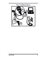
Refer to Figure 1 and follow these steps to install the scanner:
Consult your host terminal manual to determine if power must be
turned off before connecting peripheral devices such as the scanner.
1.
Should you need to disconnect the interface (I/F) cable from
the scanner, loosen the Phillips head screw at the bottom of
the handle and rotate the cable restraint clip away from the
cable to release it. Reverse this procedure to connect the
cable.
2.
Connect the I/F cable to the proper port on the host terminal.
3.
If your system requires an AC/DC adapter to power the
scanner, connect the adapter's power cord at the I/F connec-
tor. (Note: In most cases, the scanner uses Power Off the Ter-
minal [P.O.T.], and does not require this step.) Contact your
Datalogic dealer if you’re not sure if an AC/DC adapter
should be used with your system.
4.
Connect the AC/DC adapter at the wall outlet. (P.O.T. units
skip this step.)
5.
Verify operation—point at a flat surface and pull the trigger.
A red beam should be visible. Scan a sample bar code and
confirm that the scanner reads the bar code by beeping and/
or sending the data to the host terminal.
Power Supply
Models require either a Listed class II or class III with a Limited
Power Source (LPS).
For the safety certification to be valid, class III input power sources
must be IEC/EN60950-1 (EN 60335-series, EN 60065 or relevant)
approved.
Input: 100 - 240 VAC Output: 9 - 10 VDC
Max. Current: 2.0 A Max. Power: 20 W
CAUTION
Do not attempt to pull the End Cap off, as this may
damage the scanner.


