10
PowerScan
®
RF
Scanner
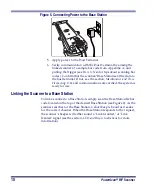
Figure 5. Connecting Power to the Base Station
5.
Apply power to the Host Terminal.
6.
Verify communication with the Host Terminal by aiming the
linked scanner at a sample bar code from Appendix A, and
pulling the trigger (see How to Scan for tips about scanning bar
codes). Confirm that the scanner/Base Station sent the data to
the host terminal. If not, see the section, Maintenance and Trou-
bleshooting. Once all communications are verified, the system is
ready for use.
Linking the Scanner to a Base Station
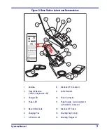
To link a scanner to a Base Station, simply scan the Base Station ID bar
code located on the top of the desired Base Station (see Figure 2). As the
scanner searches for the Base Station, a short beep is heard as it seeks
for the correct channel. When the Base Station responds to the request,
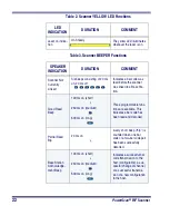
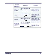
the scanner’s beeper will either sound a "Link Granted," or "Link
Denied" signal (see the section, LED and Beeper Indications for more
information).
Summary of Contents for PowerScan RF
Page 1: ...PowerScan RF Systems Manual...
Page 60: ...56 PowerScan RF Scanner 10 Retries 11 Retries 12 Retries 13 Retries 14 Retries 15 Retries END...
Page 71: ...Systems Manual 67 DISABLE Common Configuration END...
Page 80: ...76 PowerScan RF Scanner NOTES...
Page 82: ...78 PowerScan RF Scanner NOTES...
Page 85: ...Systems Manual B 1 Appendix B Number Pad 0 1 2 3 4 5 6 7 8 9...
Page 86: ...B 2 PowerScan RF Scanner NOTES...


