Systems Manual
21
LED and Beeper Indications
The Base Station LED indicators and the scanner’s LEDs and beeper
are used to announce system status and perform other useful signals.
The tables below list the default function of each of the various indica-
tors.
Table 1. Scanner GREEN LED Functions
NOTE
Some LED and beeper indications can be disabled
or modified via scanner programming. The tables
indicate the default behavior of the indicators, with
shaded rows representing features that are pro-
grammable.
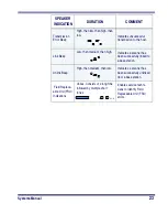
LED
INDICATION
DURATION
COMMENT
Disable
Indication
100ms on, 900 ms off
Indicates the scanner has
been disabled.
Good Read
Indication
500 ms on
Indicates a bar code has
been read and decoded.
Program Mode
Indication
500 ms on, 500 ms off
Continuous flashing
Indicates the scanner is in
Programming Mode.
Field Replace-
able Unit (FRU)
Indications
Varies. Consists of a long flash
followed by multiple short
flashes.
Enables service techni-
cians to identify Field
Replaceable Unit (FRU)
errors.
Low Battery
Indication
Two flashes at 100 ms on, 350
ms off.
Occurs at trigger pull before
the laser is enabled. Indi-
cates the battery is in need
of recharging.
Summary of Contents for PowerScan RF
Page 1: ...PowerScan RF Systems Manual...
Page 60: ...56 PowerScan RF Scanner 10 Retries 11 Retries 12 Retries 13 Retries 14 Retries 15 Retries END...
Page 71: ...Systems Manual 67 DISABLE Common Configuration END...
Page 80: ...76 PowerScan RF Scanner NOTES...
Page 82: ...78 PowerScan RF Scanner NOTES...
Page 85: ...Systems Manual B 1 Appendix B Number Pad 0 1 2 3 4 5 6 7 8 9...
Page 86: ...B 2 PowerScan RF Scanner NOTES...


