background image

48

PowerScan

®

 RF 

Scanner

RF Beeper

Volume

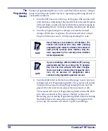
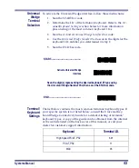
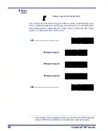
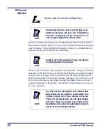
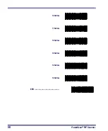
The volume at which the beeper sounds for ACK, transmission error, 
link, or unlink beeps (but not the good read beep

1

) are all affected by 

this setting. Select volume #1 (25% duty cycle), volume #2 (35% duty 
cycle), or volume #3 (50% duty cycle).

Feature is specific to scanner ONLY

1. Good read beep volume is selectable via the features available in the PowerScan Programming 

Manual (P/N R44-1840). See References for information about acquiring other manuals.

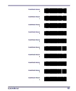
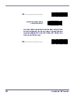
SET ------------------------------------------- 

RF Beeper Volume #1

RF Beeper Volume #2

RF Beeper Volume #3

END ------------------------------------------ 

Summary of Contents for PowerScan RF

Page 1: ...PowerScan RF Systems Manual...

Page 2: ...4971177 4991692 5001406 5015831 5019697 5019698 5086879 5115120 5144118 5146463 5179270 5198649 5200597 5202784 5208449 5210397 5212371 5212372 5214270 5229590 5231293 5232185 5233169 5235168 5237161...

Page 3: ...ow to Scan 15 Depth of Field 16 Active Symbologies 20 Enhanced Scanning for Hard to Read Bar Codes 20 LED and Beeper Indications 21 Maximizing Signal Range 25 Three Position Lock 26 Mounting the Base...

Page 4: ...65 Common Configuration 66 Set Maximum Linked Scanners 68 Source Radio Identification ID 70 Low Battery LED Indication 72 Maintenance and Troubleshooting 73 Scanner Maintenance 73 Base Station Mainte...

Page 5: ...tem configuration that is unique to the RF system Maintenance and Troubleshooting provides solutions for prob lems that may be encountered during installation and use of the system Standard Warranty...

Page 6: ...applicable information view the labels on the product itself or call your nearest sales or service representative CAUTION LASERRADIATIONWHENOPEN AVOIDEXPOSURETOBEAM COVERED BYONEORMOREOFTHE FOLLOWING...

Page 7: ...y Slots 3 7 3 Position Lock 14 Mounting Flanges 4 MODEL PowerScan RF Base Station CLASS No SERIAL No FREQ ACN N263 C US LISTED NWGQ 2Z78 This device complies with Part 15 of the FCC Rules Operation is...

Page 8: ...ions CAUTION In the unlikely event that a bright laser spot is expe rienced rather than a scan line do not stare into the beam or attempt to repair the unit Discontinue operation and return the unit t...

Page 9: ...t harmful interference in a residential installation This equipment generates uses and can radiate radio frequency energy and if not installed and used in accordance with these instructions may cause...

Page 10: ...r missing components contact your place of purchase If there are damaged components immediately file a claim with the carrier You may want to save your packing material in case you need to ship the sc...

Page 11: ...ce To remove the battery push in on the release tabs on both sides of the battery s base and pull it straight out of the scan ner Figure 3 Installing the Battery NOTE To assure maximum usage batteries...

Page 12: ...shooting Connecting the Base Station to the Host Terminal 1 Connect the I F cable to the Base Station see Figure 4A The I F cable is inserted into the connector and the cable retainer clip is rotated...

Page 13: ...on the Host Terminal check your Host Terminal manual to determine hardware requirements 4 Connect the AC Adapter s power cord at the Base Station and plug the AC DC adapter in at the wall outlet see F...

Page 14: ...the section Maintenance and Trou bleshooting Once all communications are verified the system is ready for use Linking the Scanner to a Base Station To link a scanner to a Base Station simply scan the...

Page 15: ...If a transmission error beep warble is heard follow ing a good read tone instead of the single acknowledgement tone communication between the devices may have failed2 Refer to the sec tions Using the...

Page 16: ...een 10 C 50 F and 46 C 115 F and or voltage of the battery is between 2 0 and 3 2V Charge time is less than 4 2 hours Rapid charge ends with the battery at approximately 90 to 95 capacity The CHARGE L...

Page 17: ...ents for NiMH batteries so when they won t hold a charge anymore the batteries can be disposed of preferably through a recycling center Four Station Charger If you have a Four Station Charger batterie...

Page 18: ...14 PowerScan RF Scanner Figure 7 Using the Four Station Charger Accessory 1 Device Power LED 2 Station Charge LEDs 1 2...

Page 19: ...anning results 1 The scanner must be pointed at a slight angle to the bar code Do not hold the scanner perpendicular to the bar code 2 The laser beam must cross the entire bar code The scanner cannot...

Page 20: ...0 001 inches In the context of the illustrations in this section a mil represents the minimum bar code element width Thus a 5 mil bar code would have a minimum element width of 5 mils or 0 005 inches...

Page 21: ...s set with the standard 28 scan width as opposed to the Half Angle setting of 14 Reference the Programming Manual for more information about the Half Angle feature Specifications are subject to change...

Page 22: ...to change without notice Depth of Field Paper Labels LR decoded model Code 39 0 40 mil 20 mil 15 mil 7 5 mil CENTIMETERS FEET FRONT OF SCANNER 10 1 2 3 4 5 20 30 40 50 60 70 80 90 100 110 120 130 140...

Page 23: ...Field Paper Labels XLR decoded model Code 39 0 40 mil 20 mil CENTIMETERS FEET FRONT OF SCANNER 1 2 3 4 5 6 7 8 9 10 11 12 13 14 15 450 400 350 300 250 200 150 100 50 55 mil Reflective Labels XLR decod...

Page 24: ...gs you or another user have made changes to scanner program ming Enhanced Scanning for Hard to Read Bar Codes Decoded scanners can be programmed to decode extremely poor qual ity bar codes by activati...

Page 25: ...features that are pro grammable LED INDICATION DURATION COMMENT Disable Indication 100ms on 900 ms off Indicates the scanner has been disabled Good Read Indication 500 ms on Indicates a bar code has b...

Page 26: ...as linked to a Base Sta tion Good Read Beep 100 ms on short 250 ms on medium 500 ms on long Three programmable func tions are available This indicates a bar code has been read and decoded Partial Read...

Page 27: ...ner has been successfully linked to a base station Unlink Beep High then medium then low Indicates a scanner has been successfully unlinked from a base station Field Replace able Unit FRU Indications...

Page 28: ...power up Indicates a broken radio Varies Consists of a long flash followed by multiple short flashes Enables service techni cians to identify Field Replaceable Unit FRU errors Charge Battery Continuou...

Page 29: ...ent at various elevations orientations etc to achieve better communications between devices The system usually works best at heights of one meter or more off the ground Usually the scanner and Base St...

Page 30: ...ree position lock to allow a scan ner to be secured in the Base Station in horizontal vertical and forklift installations Figure 13 Using the Three Position Lock 1 Top position Vertical Forklift Mount...

Page 31: ...25 4mm pan head self tapping screws in the marked positions until completely threaded into the mounting surface then back the screws off two to three full turns 3 Ensure that power and interface cable...

Page 32: ...e mounting flanges Base Station attachment is now complete Figure 15 Mounting Using Flanges or Two sided Tape Mounting Using Two Sided Tape You can also affix the Base Station to a surface using the t...

Page 33: ...l 29 Using Key Slots Using Mounting Flanges Mounting Using Two Sided Tape 1 1 Since mounting using this method offers less secure attachment verify that your tape installation is robust enough for you...

Page 34: ...l not present a hazard for opera tors or potentially damage the mounted device s 2 Ensure that power and interface cables are securely connected and routed in the channels provided in the back of the...

Page 35: ...e Return to Factory Settings Interface I F Selection RF Beeper Settings Radio Transmit Power RF Channel Selection Transmission Retries Before Message Time out Wait Time for ACK Wait Time For Scanner P...

Page 36: ...e easiest most comprehensive way to program the scanner is to use the Configurator Express On Screen Programming Kit See References for more information about this product 3 The scanner can be configu...

Page 37: ...r Indications for information about scanner indications while in Programming Mode CAUTION Verify that the scanner and Base Station host inter face types RS 232 Keyboard Wedge etc are matched before at...

Page 38: ...eset upon exiting Programming Mode and the green LED will return to its usual state on steady or off The scanner will not exit Programming Mode unless the END bar code is scanned or the scanner s batt...

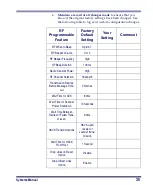
Page 39: ...tion 7 RF Beeper Volume Vol 3 RF Beeper Frequency High RF Beep Duration 100ms Radio Transmit Power High RF Channel Selection Channel 5 Transmission Retries Before Message Time out 3 Retries Wait Time...

Page 40: ...Mode and an Item Tag1 is scanned Then a value must be entered before ending the pro gramming session In the example three digits must be scanned from the number pad in Appendix B This type of for mat...

Page 41: ...e 5 Programming Sequence 1 1 C A B 2 3 1 2 3 4 5 6 SET SET ENABLE NEW FEATURE ENABLE NEW FEATURE USING THE FOLLOWING SETTINGS END SET END 0 8 ITEM TAG ITEM VALUE END RESET 0 ONE BAR CODE CONTAINS SET...

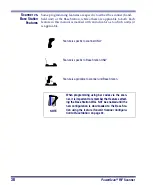
Page 42: ...s to which unit s it is applicable Feature is specific to scanner ONLY Feature is specific to Base Station ONLY Feature is applicable to scanner and Base Station NOTE When programming using bar codes...

Page 43: ...onfiguration you may need to contact your sale representative for assistance to return the unit to normal function Please be prepared to provide infor mation about the company location host terminal s...

Page 44: ...interface I F type as the host terminal NOTE The Base Station uses a smart cable which auto matically sets the Base Station to the correct I F upon power up and connection to the appropriate host SET...

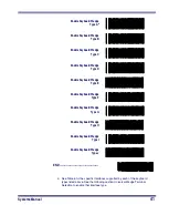
Page 45: ...d Wedge Type E Enable Keyboard Wedge Type F Enable Keyboard Wedge Type G Enable Keyboard Wedge Type H Enable Keyboard Wedge Type I Enable Keyboard Wedge Type J END a See Table 6 for the specific inter...

Page 46: ...6 30 286 50 50Z 60 70 80 90 95 w Alternate Key Encoding C PS 2 25 and 30 w Alternate Key Encoding D PC XT w Standard Key Encoding E AT PS 2 25 286 30 286 50 50Z 60 70 80 90 95 w Standard Key Encoding...

Page 47: ...in step 2 5 Scan the END bar code Terminal Keyboard Settings The list below contains the most common terminal keyboard types If your specific system is not listed below consult the Universal Key board...

Page 48: ...e factory settings is Keyboard Wedge of PC AT keyboard I D 11 Use the codes on this page to select the I D corresponding to your computer or terminal reference the Uni versal Keyboard Wedge Connectivi...

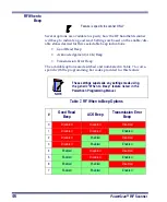
Page 49: ...hange sequence or a successful configuration transmission Transmission Error Beep Another selectable indicator beep is the transmission error beep This beep sounds to indicate an error in trans missio...

Page 50: ...in Table 7 to corre spond with the programming bar codes provided for this feature Table 7 RF When to Beep Options Feature is specific to scanner ONLY NOTE These settings supersede any settings made...

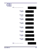
Page 51: ...RF When to Beep Options continued SET When to Beep Option 0 When to Beep Option 1 When to Beep Option 2 When to Beep Option 3 When to Beep Option 4 When to Beep Option 5 When to Beep Option 6 When to...

Page 52: ...by this setting Select volume 1 25 duty cycle volume 2 35 duty cycle or volume 3 50 duty cycle Feature is specific to scanner ONLY 1 Good read beep volume is selectable via the features available in...

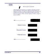
Page 53: ...r the good read beep When the ACK beep is sounded at a different frequency than the good read beep this can provide a clearer distinction between the tones Select low frequency 760Hz medium frequency...

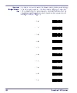
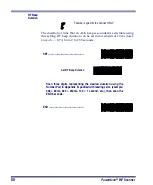
Page 54: ...duration can be set in increments of 10 ms toler ance of 10 from 0 to 2 55 seconds Feature is specific to scanner ONLY SET Set RF Beep Duration Scan three digits representing the desired duration usin...

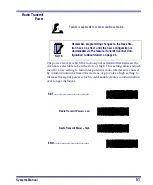
Page 55: ...by communication between the devices or provides a high setting to increase the signal power which would enable clearer communication over longer distances Feature is applicable to scanner and Base St...

Page 56: ...garding scanner and Base Station acknowl edgement signals at this point All further communication is done on the new channel Feature is applicable to scanner and Base Station NOTE Channel selection ba...

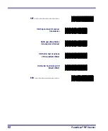
Page 57: ...Radio Channel 0 Select Radio Channel 1 Select Radio Channel 2 Select Radio Channel 3 Select Radio Channel 4 Select Radio Channel 5 Select Radio Channel 6 Select Radio Channel 7 Select Radio Channel 8...

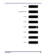
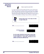
Page 58: ...eeded the scan ner will sound a transmission error beep when transmission error beep is enabled In a noisy RF environment a large number of retries may allow a trans mission to get through to the Base...

Page 59: ...Systems Manual 55 2 Retries 3 Retries recommended 4 Retries 5 Retries 6 Retries 7 Retries 8 Retries 9 Retries...

Page 60: ...56 PowerScan RF Scanner 10 Retries 11 Retries 12 Retries 13 Retries 14 Retries 15 Retries END...

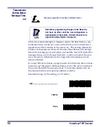
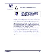
Page 61: ...ts Feature is applicable to scanner and Base Station NOTE Remember programming changes to the Base Sta tion have no effect until the new configuration is downloaded via the feature Transmit Scanner Co...

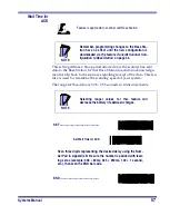
Page 62: ...tive after each use Range for this feature is a setting of 1 to 120 seconds in one second increments A setting of one second is recommended Feature is specific to scanner ONLY NOTE Selecting higher va...

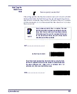
Page 63: ...time required to successfully transmit the message Wait range can be set from 5ms to 255ms in one millisecond incre ments and is multiplied by the amount of retries selected via the fea ture TRANSMIS...

Page 64: ...Between Retries of Failed Transmission Scan three digits representing the desired delay using the Num ber Pad in Appendix B Be sure the number is padded with lead ing zeros example 005 5ms 065 65ms 25...

Page 65: ...nners are linked to one Base Station Send HACK as soon as the Base Station completes transmis sion to the host This option is recommended for installations where only a single scanner is linked to one...

Page 66: ...werScan RF Scanner SET HACK upon receipt of scanner transmission HACK upon Base Station transmission to the host HACK after host transitions CTS line RS 232 ONLY HACK after host returns ACK RS 232 ONL...

Page 67: ...re is specific to scanner ONLY NOTE Host turnaround ACK time is variable This item HACK should be set based on settings for the fea tures Wait Time for ACK and Transmission Retries Before Message Time...

Page 68: ...sure that when reconfiguring a system scanners do not need to be located and individually unlinked Feature is specific to Base Station ONLY NOTE Remember programming changes to the Base Sta tion have...

Page 69: ...ys tem to make room for the new scanner When this feature is disabled scanners can be linked up to the maxi mum number set via the programming feature Set Maximum Linked Scanners or the default maximu...

Page 70: ...Scanner Configuration to Base Station bar code Base Station on page 33 Feature is applicable to scanner and Base Station NOTE Remember programming changes to the Base Sta tion have no effect until th...

Page 71: ...Systems Manual 67 DISABLE Common Configuration END...

Page 72: ...gnate a number of scanners that can link from one to eight Feature is specific to Base Station ONLY NOTE Remember programming changes to the Base Sta tion have no effect until the new configuration is...

Page 73: ...Systems Manual 69 Maximum Linked Scanners 5 Maximum Linked Scanners 6 Maximum Linked Scanners 7 Maximum Linked Scanners 8 END...

Page 74: ...Base Station ONLY NOTE Remember programming changes to the Base Sta tion have no effect until the new configuration is downloaded via the feature Transmit Scanner Con figuration to Base Station on pag...

Page 75: ...Systems Manual 71 SET Do not include source radio ID Include source radio as prefix Include source radio as suffix END...

Page 76: ...this feature is enabled and the battery power in the scanner is low the scanner s green LED flashes twice every time the trigger is pulled Feature is specific to scanner ONLY SET ENABLE Low Battery L...

Page 77: ...e Scan Window Base Station Maintenance The Base Station requires no routine maintenance If the antenna becomes damaged a kit is available for its replacement Use only Data logic replacement antenna ki...

Page 78: ...nnels the Base Station is powered on You can verify the Base Sta tion s AC Adapter by using a known good AC Adapter the Base Station interface cable is securely attached to the host Consult your techn...

Page 79: ...r more information Links may be dropped by the Base Station if it has been reset power cycled It may be necessary to relink all scanners upon system reset See also Drop Links on Reset Option CAUTION T...

Page 80: ...76 PowerScan RF Scanner NOTES...

Page 81: ...ith product manual installation or service of product by other than Datalogic representatives use of product with any other instrument equipment or apparatus modification or alteration of product Exte...

Page 82: ...78 PowerScan RF Scanner NOTES...

Page 83: ...codes to check the scanner s ability to read the vari ous symbologies represented Code 128 Code 39 Interleaved 2 of 5 Standard 2 of 5 Codabar Code 93 C o d e 1 2 8 T e s t C O D E 3 9 T E S T 0 1 2 3...

Page 84: ...ey UPC A UPC A with 2 digit Add on UPC A with 5 digit Add on UPC E EAN 8 EAN 13 14476925 4 0 0 0 1 1 2 2 3 3 4 4 0 4 9 0 6 0 9 9 2 0 1 1 1 8 7 6 9 0 0 0 0 0 8 0 2 9 5 1 0 4 1 8 0 9 9 8 8 7 5 0 0 0 2 1...

Page 85: ...Systems Manual B 1 Appendix B Number Pad 0 1 2 3 4 5 6 7 8 9...

Page 86: ...B 2 PowerScan RF Scanner NOTES...

Page 87: ...ere relevante voorzieningen van EU richtlijn 1999 5 EC Suomalainen T m laite noudattaa direktiivin 1999 5 EC keskeisi vaatimuksia ja sen muita olennaisia m r yksi Fran ais Cet quipement r pond aux exi...

Page 88: ...39 6859496 Japan Datalogic Scanning KK Shinagawa Tokyo Japan Telephone 81 0 3 3491 6761 Fax 81 0 3 3491 6656 Latin America Datalogic Scanning Inc Miami Florida USA Telephone 305 591 3222 Fax 305 591 3...

Reviews: