Systems Manual
3
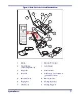
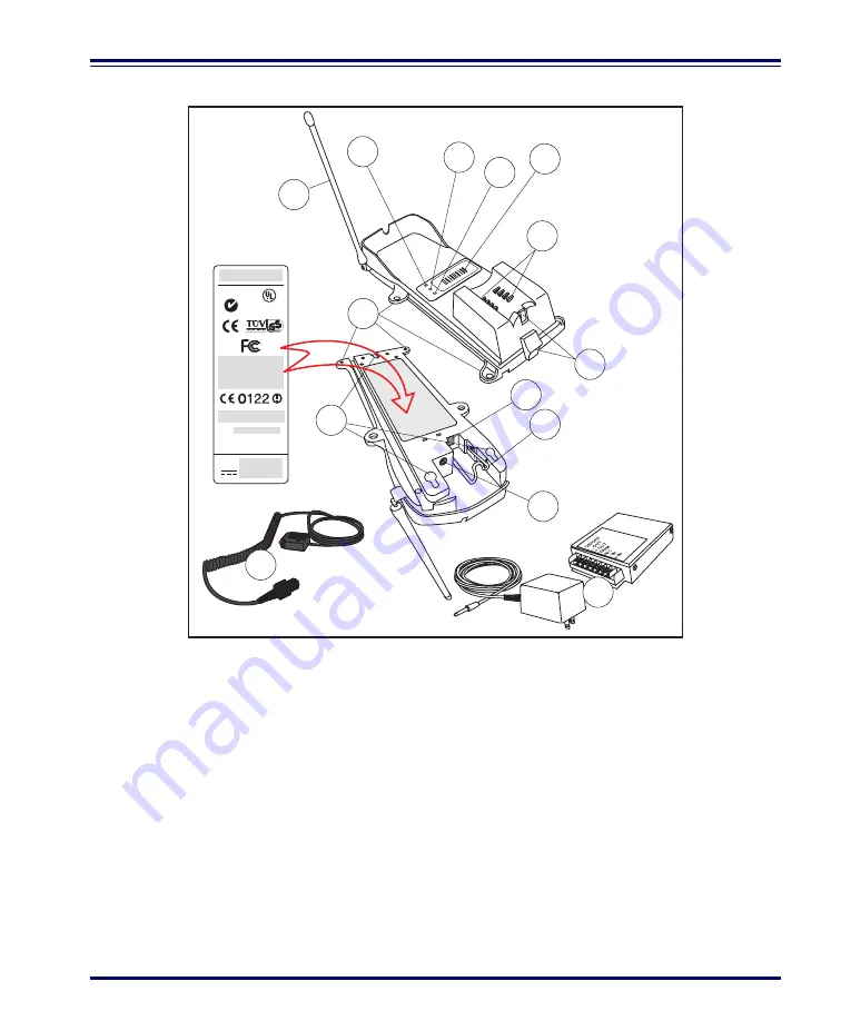
Figure 2. Base Station Labels and Nomenclature
1.
Antenna
8.
Interface (I/F) Connector
2.
Transmit/Receive
(TX/RX)/ Diagnostics LED
9.
Cable Retainer
3.
Charge LED
10
Power Connector
4.
Power LED
11.
Power Supply - (a) AC Adapter or
(b) Forklift DC Converter
5.
Base ID Bar Code
12.
Interface (I/F) Cable
6.
Charging Pins
13.
Mounting Key Slots (3)
7.
3-Position Lock
14.
Mounting Flanges (4)
MODEL: PowerScan RF Base Station
CLASS No.
SERIAL No.
FREQ:
ACN
N263
C
US
LISTED
NWGQ 2Z78
This device complies with Part 15 of the FCC Rules.
Operation is subject to the following two conditions:
1. This device may not cause harmful interference.
2. This device must accept any interference, including
interference that may cause undesired operation.
Applicable patents are listed on label inside handheld unit.
Product of USA
BASE ID
TX/RX
CHARGE
PO
WER
1
2
3
4
5
6
7
13
8
9
10
14
12
11
a
b
Summary of Contents for PowerScan RF
Page 1: ...PowerScan RF Systems Manual...
Page 60: ...56 PowerScan RF Scanner 10 Retries 11 Retries 12 Retries 13 Retries 14 Retries 15 Retries END...
Page 71: ...Systems Manual 67 DISABLE Common Configuration END...
Page 80: ...76 PowerScan RF Scanner NOTES...
Page 82: ...78 PowerScan RF Scanner NOTES...
Page 85: ...Systems Manual B 1 Appendix B Number Pad 0 1 2 3 4 5 6 7 8 9...
Page 86: ...B 2 PowerScan RF Scanner NOTES...


