RF Programming Manual
5
To determine if your desired new interface is available on your scanner,
check the following section titled
Software
on page 7. The section lists
host interface types supported by each interface board available at the
time of this writing. If you are still unsure of your scanner’s available
interface connectivity, consult your Datalogic dealer.
The Base Station will need to be sent to an authorized service repair
depot if the interface board must be swapped; however, if necessary,
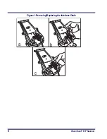
you can change your Base Station’s interface (I/F) cable by following
these instructions. (Refer to Figure 1.):
1.
Power down the system.
2.
Disconnect the I/F cable from the host terminal.
3.
Swing the I/F cable retainer up (as shown in Figure 1a) to free
the cable.
4.
Disconnect the cable (Figure 1b).
5.
Connect the replacement I/F cable to the Base Station.
6.
Rotate the cable retainer over the cable overmold until the
retainer snaps in place (see Figure 1c).
NOTE
It is important that the I/F cable be connected to the
Base Station prior to applying power to the system.
This is because the interface type (RS-232, IBM, Key-
board Wedge, etc.) is selected by the Base Station
subject to the I/F cable it is connected to at the time
of power-up.
NOTE
Once the system is connected and powered-on, link
the scanner(s) by following the instructions given in
the Section,
Linking the Scanner to a Base Station
on page 150. The Base Station will automatically
download its new interface setting to the scanner
during the process of linking.
Summary of Contents for PowerScan RF
Page 1: ...PowerScan RF Programming Guide ...
Page 6: ...iv Magellan 8300 8400 ...
Page 12: ...6 PowerScan RF Scanner Figure 1 Removing Replacing the Interface Cable b c a ...
Page 47: ...RF Programming Manual 41 H I J END Transmit Scanner Configuration to Base Station ...
Page 89: ...RF Programming Manual 83 Digits 0 1 2 3 4 5 6 7 8 9 ...
Page 95: ...RF Programming Manual 89 Digits 0 1 2 3 4 5 6 7 8 9 ...
Page 104: ...98 PowerScan RF Scanner Digits 0 1 2 3 4 5 6 7 8 9 ...
Page 114: ...108 PowerScan RF Scanner Digits 0 1 2 3 4 5 6 7 8 9 ...
Page 133: ...RF Programming Manual 127 Deactivate for EAN 8 END ...
Page 136: ...130 PowerScan RF Scanner END Digits 0 1 2 3 4 5 6 7 ...
Page 144: ...138 PowerScan RF Scanner Digits 0 1 2 3 4 5 6 7 8 9 ...
Page 153: ...RF Programming Manual 147 Digits 0 1 2 3 4 5 6 7 8 9 ...
Page 161: ...RF Programming Manual 155 RF Beeper Volume 1 RF Beeper Volume 2 RF Beeper Volume 3 END ...
Page 200: ...194 PowerScan RF Scanner 9 0 A B C D E F ...
Page 208: ...202 PowerScan RF Scanner NOTES ...
Page 213: ...RF Programming Manual 207 NOTES ...
Page 214: ...208 PowerScan RF Scanner NOTES ...


