RF Programming Manual
13
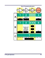
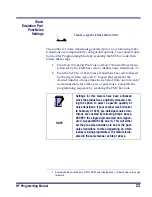
The
Programming
Session
Scanner programming allows you to customize the scanner’s configu-
ration to match your specific needs. A typical programming session is
conducted as follows:
1.
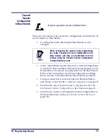
Scan the SET bar code at the top of the page. The scanner will
emit one beep, indicating it has read the bar code and the green
LED will flash on and off slowly while the scanner remains in
Programming Mode. Normal scanning functions are disabled.
2.
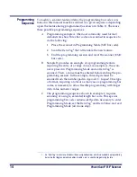
Scan the programming bar code(s) to make the desired
changes. With few exceptions, the scanner will emit a triple
beep each time you scan a valid programming bar code.
3.
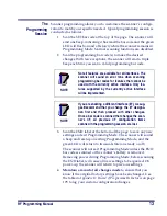
Scan the END label at the bottom of the page to save any new
settings and exit Programming Mode. The scanner will sound
a beep and reset upon exiting Programming Mode, and the
green LED will return to its usual state (on steady or off).
The scanner will not exit Programming Mode unless the END
bar code is scanned or the scanner’s battery is removed.
Removing power during Programming Mode, before scanning
the END label, will cause all new settings to be ignored. On
power-up, the scanner will return to previous settings.
4.
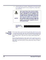
Maintain a record of all changes made
to ensure that you
know if the original factory settings have been changed. Use
the table in
Appendix D: Record of Programmable Features
on page
195 to log your custom configuration changes
NOTE
Not all features are available for all interfaces. The
scanner will sound an error tone when scanning
programming bar codes for features that cannot be
used with the currently active interface. Only fea-
tures supported by the currently active interface
will be implemented.
NOTE
If you are enabling a different interface (I/F), we sug-
gest/recommend that you change the I/F designa-
tion first and then proceed with other changes.
Once a bar code is scanned that changes the scan-
ner's I/F, all previous I/F configuration items
scanned in the programming session are lost.
Summary of Contents for PowerScan RF
Page 1: ...PowerScan RF Programming Guide ...
Page 6: ...iv Magellan 8300 8400 ...
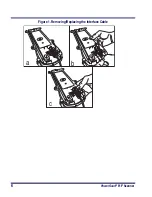
Page 12: ...6 PowerScan RF Scanner Figure 1 Removing Replacing the Interface Cable b c a ...
Page 47: ...RF Programming Manual 41 H I J END Transmit Scanner Configuration to Base Station ...
Page 89: ...RF Programming Manual 83 Digits 0 1 2 3 4 5 6 7 8 9 ...
Page 95: ...RF Programming Manual 89 Digits 0 1 2 3 4 5 6 7 8 9 ...
Page 104: ...98 PowerScan RF Scanner Digits 0 1 2 3 4 5 6 7 8 9 ...
Page 114: ...108 PowerScan RF Scanner Digits 0 1 2 3 4 5 6 7 8 9 ...
Page 133: ...RF Programming Manual 127 Deactivate for EAN 8 END ...
Page 136: ...130 PowerScan RF Scanner END Digits 0 1 2 3 4 5 6 7 ...
Page 144: ...138 PowerScan RF Scanner Digits 0 1 2 3 4 5 6 7 8 9 ...
Page 153: ...RF Programming Manual 147 Digits 0 1 2 3 4 5 6 7 8 9 ...
Page 161: ...RF Programming Manual 155 RF Beeper Volume 1 RF Beeper Volume 2 RF Beeper Volume 3 END ...
Page 200: ...194 PowerScan RF Scanner 9 0 A B C D E F ...
Page 208: ...202 PowerScan RF Scanner NOTES ...
Page 213: ...RF Programming Manual 207 NOTES ...
Page 214: ...208 PowerScan RF Scanner NOTES ...

