Systems Manual
27
Mounting the Base Station
The Base Station can be secured to varying surfaces to ensure a perma-
nent, stable installation. Several options are available.
Horizontal (Table or Countertop) Mounting
Using Key
Slots
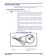
Refer to Figure 14 and follow these steps:
1.
Once you have identified the desired area for permanent Base
Station installation, use the mounting template included with
this manual to mark the position of its "key slot" mounting
screws.
2.
Install three #8 x 1" (4.1mm x 25.4mm) pan head, self-tapping
screws in the marked positions until completely threaded into
the mounting surface, then back the screws off two to three full
turns.
3.
Ensure that power and interface cables are securely connected
and routed in the channels provided in the bottom of the Base
Station.
4.
Align the Base Station key slots (wide end) with the screws,
then slide the Base Station to position the screws in the smaller
ends of the key slots. Adjust the height of the mounting screws
if needed for a secure fit. The Base Station is now secured to the
table or countertop.
Figure 14. Mounting Using Key Slots
1.
Key Slots
2.
#8 x 1" (4.1mm x 25.4mm) Pan
Head Screw
BAS
E ID
TX/R
X
CH
AR
GE
PO
WE
R
1
2
Summary of Contents for PowerScan RF
Page 1: ...PowerScan RF Systems Manual...
Page 60: ...56 PowerScan RF Scanner 10 Retries 11 Retries 12 Retries 13 Retries 14 Retries 15 Retries END...
Page 71: ...Systems Manual 67 DISABLE Common Configuration END...
Page 80: ...76 PowerScan RF Scanner NOTES...
Page 82: ...78 PowerScan RF Scanner NOTES...
Page 85: ...Systems Manual B 1 Appendix B Number Pad 0 1 2 3 4 5 6 7 8 9...
Page 86: ...B 2 PowerScan RF Scanner NOTES...


