background image


AMT58x-CB CANopen®


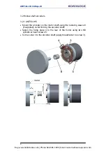
3.1.3 Installation using a flange (code ST-58-FLNG) 


Buy: www.ValinOnline.com | Phone 844-385-3099 | Email: CustomerService@valin.com

Summary of Contents for Profibus AMT58 13x12 PB Series

Page 1: ...Buy www ValinOnline com Phone 844 385 3099 Email CustomerService valin com...

Page 2: ...omation S r l Datalogic and the Datalogic logo are registered trademarks di Datalogic S p A in many countries including the U S A and the E U Tutti i marchi e i nomi di prodotti qui citati servono al...

Page 3: ...interface 16 6 1 EDS file 16 6 2 Operation states 16 6 2 1 Initialization state 17 6 2 2 Pre operational state 17 6 2 3 Operational state 17 6 2 4 Stopped state 17 6 3 Communication objects 18 6 3 1 P...

Page 4: ...imit switch min 32 Limit switch max 32 6001 00 Counts per revolution 32 6002 00 Total resolution 33 6003 00 Preset value 34 6200 00 Cyclic time 35 6500 00 Operating states 35 Code sequence 35 Scaling...

Page 5: ...g parameters 32 6001 00 Counts per revolution 32 6002 00 Total resolution 33 6003 00 Preset value 34 6004 00 Position value 35 6200 00 Cyclic time 35 6500 00 Operating states 35 6501 00 Hardware count...

Page 6: ...where information of great significance for the user can be found user must pay the greatest attention to them Instructions must be followed strictly in order to guarantee the safety of the user and...

Page 7: ...the first section general information concerning the safety the mechanical installation and the electrical connection as well as tips for setting up and running properly and efficiently the unit are p...

Page 8: ...g the device connect according to explanation in section 4 Electrical connections in compliance with the 2004 108 EC norm on electromagnetic compatibility following precautions must be taken before ha...

Page 9: ...haracteristics declared by manufacturer unit with solid shaft in order to guarantee maximum reliability over time of mechanical parts we recommend a flexible coupling to be installed to connect the en...

Page 10: ...s listed in the delivery document too Please always quote the ordering code and the serial number when reaching Datalogic Automation s r l for purchasing spare parts or needing assistance For any info...

Page 11: ...r to the flange 2 or to the mounting bell by means of screws 3 secure the flange 2 to the support or the mounting bell to the motor mount the flexible coupling 1 on the motor shaft make sure the misal...

Page 12: ...AMT58x CB CANopen 5 3 1 3 Installation using a flange code ST 58 FLNG Buy www ValinOnline com Phone 844 385 3099 Email CustomerService valin com...

Page 13: ...ng the reducing sleeve 8 if supplied Avoid forcing the encoder shaft fasten the fixing plate 4 to the rear of the motor using two M3 cylindrical head screws 5 fix the collar 3 to the encoder shaft app...

Page 14: ...ance are located inside the encoder connection cap Thus you must remove the connection cap to access any of them NOTE Be careful not to damage the internal components when you perform this operation T...

Page 15: ...se 1 TCEI M3 x 6 cylindrical head screw with 2 tooth lock washers 4 3 Connection cap The connection cap is fitted with two PG9 cable glands for bus IN bus OUT and supply voltage connections The bus ca...

Page 16: ...N Shield 1 1 2 10Vdc 30Vdc Supply voltage 3 0 Vdc Supply voltage 4 CAN High 5 CAN Low 1 CAN Shield is also connected to pin 1 to allow the connection of the shield even if the plug connector has a pla...

Page 17: ...nsmission line 4 7 Diagnostic LEDs Two diagnostic LEDs located in the rear side of the connection cap are designed to show the operating or fault status of the CANopen interface GREEN LED Description...

Page 18: ...et binary value of transmission rate considering that ON 1 OFF 0 bit 1 LSB 2 3 MSB 4 20 21 22 ON OFF Available baud rate values Decimal value Binary value Baud rate 0 000 20 Kbit s 1 001 50 Kbit s 2 0...

Page 19: ...012 binary value bit 1 2 3 4 5 6 7 8 20 21 22 23 24 25 26 ON OFF OFF ON ON OFF OFF OFF Set node number 55 5510 0011 01112 binary value bit 1 2 3 4 5 6 7 8 20 21 22 23 24 25 26 ON ON ON OFF ON ON OFF O...

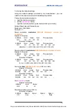
Page 20: ...t match the ordering code see encoder label then it is compulsory to set the hardware resolution for any information on reading the hardware resolution refer to section 5 2 Using the default settings...

Page 21: ...ex Sub Process data 600 ID 23 02 65 00 B4 B5 B6 B7 Encoder Master COB ID Cmd Index Sub Process data 580 ID 60 02 65 00 00 00 00 00 Step 4 Send a Reset node command Master Encoder COB ID Cmd Slave ID 0...

Page 22: ...ndex Sub Process data 581 43 01 65 01 A0 A1 A2 A3 steps rev A3 24 A2 16 A1 8 A0 Read number of revolutions 6502 00 Hardware number of turns Master Encoder COB ID Cmd Index Sub Process data 601 40 02 6...

Page 23: ...file has to be installed on CANopen master device 6 2 Operation states CANopen devices are designed to operate using different states Transition from one state to another is made by sending specific N...

Page 24: ...ssage 6 2 3 Operational state In this state slave device is active and all communication objects are available Slave device can use the parameters available in the Object dictionary and is allowed to...

Page 25: ...es to transmit process data encoder position and velocity Emergency error messages are triggered by each error event Nodeguard used to request the state of the slave Relation between device states and...

Page 26: ...es NMT Function Command NMT Function State node 01 hex Start remote node Operational 02 hex Stop remote node Stopped 80 hex Enter pre operational Pre operational 81 hex Reset node Pre operational 82 h...

Page 27: ...ral nodes encoders are connected to the network the Master receives the position values from the slaves respecting the Node number order The encoder can be programmed to send a reply after a set numbe...

Page 28: ...b index fields SDO messages are always followed by confirmation It follows that when Master sends a SDO message to Slave slave always sends a reply and a warning should an error occur SDO structure ID...

Page 29: ...essages to master e g Index does not exist Comman d COB COB type Data length 22h Set M S request not spec 23h Set M S request 4 byte 2Bh Set M S request 2 byte 2Fh Set M S request 1 byte 60h Set S M c...

Page 30: ...ard objects DS 301 1000 00 Device type Unsigned32 ro Default 0001 0196h singleturn encoder DS 406 0002 0196h multiturn encoder DS 406 1001 00 Error register Unsigned8 ro Should an error occur bit 0 in...

Page 31: ...d time Unsigned16 rw It contains the Guard time expressed in msec milliseconds Object 100C 00 Guard time is used in the Node guarding protocol controlled by the master For more details see section 6 1...

Page 32: ...lt values are set at the factory by Datalogic Automation engineers to allow the operator to run the device for standard operation in a safe mode Write load ASCII code in hexadecimal form in the data b...

Page 33: ...ed Default 0000h 1018 Identification object 01 Vendor number Unsigned32 ro 02 Product number Unsigned32 ro 03 Revision number Unsigned32 ro 1800 PDO1 parameters PDO1 message is used by default for cyc...

Page 34: ...terval in SYNC commands must be set in object 1801 PDO2 parameters sub 2 1802 PDO3 parameters PDO3 message is used by default for synchronous transmission of the position value 01 COB ID of the PDO3 U...

Page 35: ...nsmission of PDO1 PDO2 PDO3 and PDO4 messages can be enabled or disabled by setting to 0 or 1 the most significant bit MSB used by PDO object 180xh sub1 Cyclic transmission or synchronous transmission...

Page 36: ...set bit 13 of object 6000 00 Operating parameters to 1 Default 003F FFF0h 3000 00 Baud rate Unsigned8 rw This object is meant to set the baud rate transmission rate according to the following table Da...

Page 37: ...set node COB ID Cmd Slave ID 000 81 ID Set the master device to the new baud rate Encoder Master Boot up with new baud rate COB ID Cmd 700 ID 00 NOTE To save the new Baud rate value execute the store...

Page 38: ...a byte 580 ID 60 01 30 00 00 Master Encoder Reset node COB ID Cmd Slave ID 000 81 old ID Encoder Master Boot up with new Node ID COB ID Cmd 700 ID 00 NOTE To save the new Node ID value execute the sto...

Page 39: ...ed the device uses its own physical resolution see objects 6501 00 Hardware counts per revolution and 6502 00 Hardware number of turns if enabled it uses the resolution set in objects 6001 00 Counts p...

Page 40: ...lue and finally save the new parameters see object 1010 01 Store parameters 6002 00 Total resolution Unsigned32 rw This object sets a custom number of distinguishable steps over the total measuring ra...

Page 41: ...s per revolution and or 6002 00 Total resolution values change then the 6003 00 Preset value must be updated to the new resolution A new 6003 00 Preset value value is also required 6003 00 Preset valu...

Page 42: ...used 2 Scaling function Disabled Enabled 3 11 not used 12 Limit switch min posit 2104 00 Limit switch min posit 2104 00 Limit switch min 13 Limit switch max posit 2105 00 Limit switch max posit 2105...

Page 43: ...it For further information on the available states see 6 2 Operation states bit 15 0 Stopped or Pre operational state bit 15 1 Operational state 6501 00 Hardware counts per revolution Unsigned32 ro Th...

Page 44: ...cturer offset value Integer32 ro This object contains the manufacturer offset value This is the difference between the physical zero position of the encoder zero set mechanically and the zero position...

Page 45: ...6 10 Emergency objects Emergency EMCY objects are issued by the device when an internal error occurs EMCY structure IDENTIFIER CAN Data Byte COB ID hex 0 1 2 3 7 see object 1014 00 COBID EMCY Error c...

Page 46: ...time factor Node guarding is enabled if Node life time 0 If the slave does not receive a RTR message before the Node life time has expired it warns activating a Life Guarding Event Furthermore the re...

Page 47: ...00 Encoder Master Set confirmation COB ID Cmd Index Sub Process data 580 ID 60 01 60 00 00 00 00 00 Set total resolution 6002 00 Total resolution 224 0100 0000h Master Encoder Set request COB ID Cmd...

Page 48: ...ata 580 ID 60 01 18 02 00 Disable Sync mode 1801 PDO2 parameters sub 1 Read COB ID used by PDO2 Master Encoder Req request COB ID Cmd Index Sub Process data 600 ID 40 01 18 01 Encoder Master Req reply...

Page 49: ...0 B1 B2 B3 COB ID used by PDO1 B3 24 B2 16 B1 8 B0 set the most significant bit to 0 B3 0x7F Set new COB ID used by PDO1 1800 PDO1 parameters sub 1 Master Encoder Set request COB ID Cm d Index Sub Pro...

Page 50: ...3 parameters sub 2 0x01 1803 PDO4 parameters sub 1 NODEID 0xC0000480 1803 PDO4 parameters sub 2 0xFE 1A00 01 PDO1 mapping parameter 0x60040020 1A01 01 PDO2 mapping parameter 0x60040020 1A02 01 PDO3 ma...

Page 51: ...Buy www ValinOnline com Phone 844 385 3099 Email CustomerService valin com...

Page 52: ...omation S r l Datalogic and the Datalogic logo are registered trademarks di Datalogic S p A in many countries including the U S A and the E U Tutti i marchi e i nomi di prodotti qui citati servono al...

Page 53: ...perational state 15 6 2 3 Operational state 15 6 2 4 Stopped state 15 6 3 Communication objects 16 6 3 1 Pre defined connection set 16 6 4 NMT objects 17 6 5 Boot up objects 17 6 6 PDO objects 17 PDO1...

Page 54: ...30 Limit switch max 30 6001 00 Counts per revolution 30 6002 00 Total resolution 30 6003 00 Preset value 31 6004 00 Position value 32 6200 00 Cyclic time 32 6500 00 Operating state 32 Code sequence 32...

Page 55: ...parameters 29 6001 00 Counts per revolution 30 6002 00 Total resolution 30 6003 00 Preset value 31 6004 00 Position value 32 6200 00 Cyclic time 32 6500 00 Operating state 32 6501 00 Hardware counts...

Page 56: ...where information of great significance for the user can be found user must pay the greatest attention to them Instructions must be followed strictly in order to guarantee the safety of the user and...

Page 57: ...the first section general information concerning the safety the mechanical installation and the electrical connection as well as tips for setting up and running properly and efficiently the unit are p...

Page 58: ...the device connect according to explanation in section 4 Electrical connections in compliance with the 2004 108 EC norm on electromagnetic compatibility following precautions must be taken before han...

Page 59: ...haracteristics declared by manufacturer unit with solid shaft in order to guarantee maximum reliability over time of mechanical parts we recommend a flexible coupling to be installed to connect the en...

Page 60: ...s listed in the delivery document too Please always quote the ordering code and the serial number when reaching Datalogic Automation s r l for purchasing spare parts or needing assistance For any info...

Page 61: ...r to the flange 2 or to the mounting bell by means of screws 3 secure the flange 2 to the support or the mounting bell to the motor mount the flexible coupling 1 on the motor shaft make sure the misal...

Page 62: ...AMT58x CB CANopen 5 3 1 3 Installation using a flange code ST 58 FLNG Buy www ValinOnline com Phone 844 385 3099 Email CustomerService valin com...

Page 63: ...ng the reducing sleeve 8 if supplied Avoid forcing the encoder shaft fasten the fixing plate 4 to the rear of the motor using two M3 cylindrical head screws 5 fix the collar 3 to the encoder shaft app...

Page 64: ...ance are located inside the encoder connection cap Thus you must remove the connection cap to access any of them NOTE Be careful not to damage the internal components when you perform this operation T...

Page 65: ...3 x 6 cylindrical head screw with 2 tooth lock washers 4 3 Connection cap with PGs The connection cap is fitted with two PG9 cable glands for bus IN bus OUT and supply voltage connections The bus cabl...

Page 66: ...CAN Shield 1 1 2 10VDC 30VDC Supply voltage 3 0 VDC Supply voltage 4 CAN High 5 CAN Low 1 CAN Shield is also connected to pin 1 to allow the connection of the shield even if the plug connector has a...

Page 67: ...nsmission line 4 7 Diagnostic LEDs Two diagnostic LEDs located in the rear side of the connection cap are designed to show the operating or fault status of the CANopen interface GREEN LED Description...

Page 68: ...et binary value of transmission rate considering that ON 1 OFF 0 bit 1 LSB 2 3 MSB 4 20 21 22 ON OFF Available baud rate values Decimal value Binary value Baud rate 0 000 20 Kbit s 1 001 50 Kbit s 2 0...

Page 69: ...10012 binary value bit 1 2 3 4 5 6 7 8 20 21 22 23 24 25 26 ON OFF OFF ON ON OFF OFF OFF Set node number 55 5510 0011 01112 binary value bit 1 2 3 4 5 6 7 8 20 21 22 23 24 25 26 ON ON ON OFF ON ON OF...

Page 70: ...Sub Process data 581 43 01 65 01 A0 A1 A2 A3 steps rev A3 24 A2 16 A1 8 A0 Read number of revolutions 6502 00 Hardware number of turns Master Encoder COB ID Cmd Index Sub Process data 601 40 02 65 00...

Page 71: ...ite EDS file has to be installed on CANopen master device 6 2 Operation states CANopen devices are designed to operate using different states Transition from one state to another is made by sending sp...

Page 72: ...ssage 6 2 3 Operational state In this state slave device is active and all communication objects are available Slave device can use the parameters available in the Object dictionary and is allowed to...

Page 73: ...es to transmit process data encoder position and velocity Emergency error messages are triggered by each error event Nodeguard used to request the state of the slave Relation between device states and...

Page 74: ...al 81 hex Reset node Pre operational 82 hex Reset communication Pre operational 6 5 Boot up objects Boot up message structure COB ID hex 1 CAN Data Bytes 700 Node ID 00 6 6 PDO objects PDO tx messages...

Page 75: ...programmed to send a reply after a set number of SYNC messages by setting a counter The PDO message will be transmitted after having received the set number of SYNC messages For PDO2 the value of the...

Page 76: ...MSB 1byte LSB MSB Com command Index parameter index Sub parameter sub index Data parameter value 6 7 1 Command The command byte contains the type of telegram transmitted to the CAN network Three types...

Page 77: ...1 1000 00 Device type Unsigned32 ro Default 0001 0196h singleturn encoder DS 406 0002 0196h multiturn encoder DS 406 1001 00 Error register Unsigned8 ro Should an error occur bit 0 of this object will...

Page 78: ...w It contains the Guard time expressed in msec milliseconds Object is used in the Node guarding protocol controlled by the master For more details see section 6 11 Node guarding protocol Default 0000h...

Page 79: ...t values are set at the factory by Datalogic Automation engineers to allow the operator to run the device for standard operation in a safe mode Write load ASCII code in hexadecimal form in the data by...

Page 80: ...Default 0000h 1018 Identification object 01 Vendor number Unsigned32 ro 02 Product number Unsigned32 ro 03 Revision number Unsigned32 ro 1800 PDO1 parameters PDO1 message is used by default for cyclic...

Page 81: ...the PDO3 Unsigned32 rw If the node address is set using the internal dip switches i e at least one dip switch for setting the node has HIGH logic level 1 when the power is turned on this object is al...

Page 82: ...transmission can be modified setting the object 180xh sub 2 01h synchronous transmission at each SYNC command 02h synchronous transmission after two SYNC commands FEh cyclic transmission 1A00 01 PDO1...

Page 83: ...object 6000 00 Operating parameters to 1 Default 003F FFF0h 3000 00 Baud rate Unsigned8 rw This object is meant to set the baud rate transmission rate according to the following table Data byte Baud r...

Page 84: ...gned8 rw This object defines the node identifier of the device The node number is set through the object 3001 00 Node ID only if all bits of DIP B are set to OFF If one bit at least of DIP B is set to...

Page 85: ...ity format Unsigned8 rw This attribute defines the engineering units for the velocity value 00h steps s number of steps per second default 01h rpm revolutions per minute 3006 00 Velocity value Unsigne...

Page 86: ...tates counterclockwise CW and CCW rotations are viewed from shaft end Scaling function If disabled the device uses its own physical resolution see objects 6501 00 Hardware counts per revolution and 65...

Page 87: ...ry time you change the value in this object then you are required to set a new preset value see object 6003 00 Preset value and finally save the new parameters see object 1010 01 Store parameters 6002...

Page 88: ...rrors If 6001 00 Counts per revolution and or 6002 00 Total resolution values change the 6003 00 Preset value must be updated to the new resolution A new 6003 00 Preset value is also required 6003 00...

Page 89: ...sed 12 Limit switch min posit posit 13 Limit switch max posit posit 14 not used 15 Current operating state Stopped Pre operational Operational Code sequence It shows whether the code sequence is set t...

Page 90: ...states see section on page 14 bit 15 0 Stopped or Pre operational state bit 15 1 Operational state 6501 00 Hardware counts per revolution Unsigned32 ro This object defines the physical number of dist...

Page 91: ...ion relating to 6003 00 Preset value Default 0000 0000h 650A 01 Manufacturer offset value Integer32 ro This object contains the manufacturer offset value This is the difference between the physical ze...

Page 92: ...org 6 10 Emergency objects Emergency EMCY objects are issued by the device when an internal error occurs EMCY structure IDENTIFIER CAN Data Byte COB ID hex 0 1 2 3 7 see object 1014 00 COB ID EMCY Er...

Page 93: ...time factor Node guarding is enabled if Node life time 0 If the slave does not receive a RTR message before the Node life time has expired it warns activating a Life Guarding Event Furthermore the re...

Page 94: ...rmation COB ID Cmd Index Sub Process data 580 ID 60 01 60 00 00 00 00 00 Set total resolution 6002 00 Total resolution 228 1000 0000h Master Encoder Set request COB ID Cmd Index Sub Process data 600 I...

Page 95: ...ble Sync mode 1801 PDO2 parameters sub 1 Read COB ID used by PDO2 Master Encoder Req request COB ID Cmd Index Sub Process data 600 ID 40 01 18 01 Encoder Master Req reply COB ID Cmd Index Sub Process...

Page 96: ...data 580 ID 43 00 18 01 B0 B1 B2 B3 COB ID used by PDO1 B3 24 B2 16 B1 8 B0 set the most significant bit to 0 B3 0x7F Set new COB ID used by PDO1 1800 PDO1 parameters sub 1 Master Encoder Set request...

Page 97: ...0x01 1803 PDO4 parameters sub 1 NODEID 0xC0000480 1803 PDO4 parameters sub 2 0xFE 1A00 01 PDO1 mapping parameter sub 1 0x60040020 1A01 01 PDO2 mapping parameter sub 1 0x60040020 1A02 01 PDO3 mapping p...

Reviews: