PWR-480W INSTALLATION MANUAL
8
4
4 ELECTRICAL CONNECTIONS
4.1 DC VOLTAGE TERMINAL BLOCK
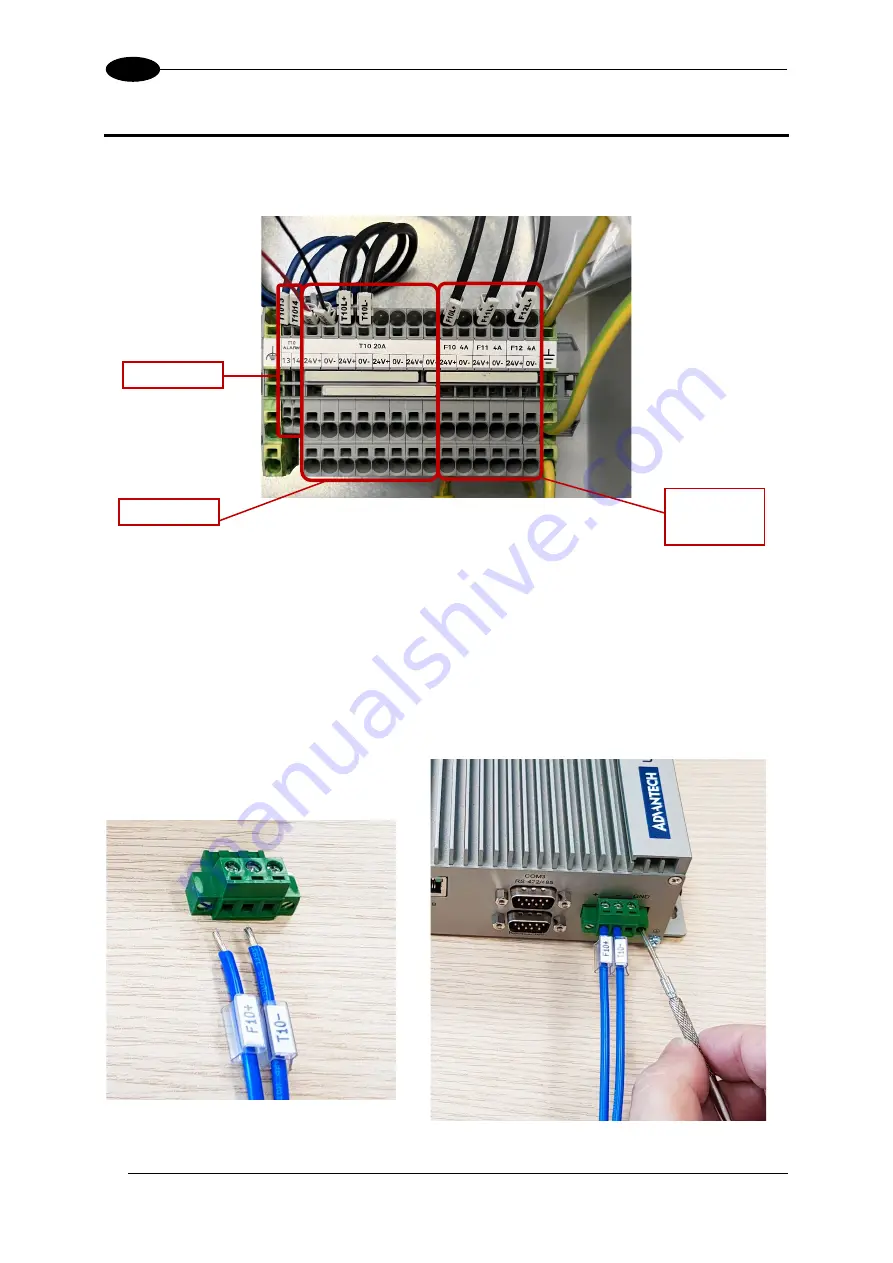
Figure 10 - PWR-480W DC Output Power Connections
The F11 and F12 sections are used to power the Master and Slave DM3610
units
respectively.
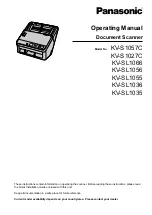
The F10 section is used to power the DC3000 unit. The F10+ and T10- cables are pre-
installed on one end in the PWR-480W terminal block as shown in Figure 10. The other end
of the F10+ cable must be inserted in the left contact hole of the connector (available in the
DC3000 package), while the other end of the T10- cable must be inserted in the central
contact hole (refer to the pictures below). The connector must then be mounted to the
DC3000 unit and tightened with the provided side screws.
Figure 11 - DC3000 connection
DC OK signals
DC Outputs
4 A MCB
protected DC
Outputs


