
TECHNICAL SPECIFICATIONS
ELECTRICAL FEATURES
QL300
QL500
Supply Voltage
10 to 30 Vdc
(see Voltage Drop below)
Consumption
-
210 mA - 70 mA
Maximum Distributed Current
Allowed
see related reading device
manual for consumption
4 A
Inputs
see relative reader Reference Manual
Outputs
see relative reader Reference Manual
PHYSICAL FEATURES
Mechanical Dimensions
129 x 76 x 27 mm
(5.1 x 3 x 1.1 in.)
Weight 312
g.
(11 oz.)
309
(10.9 oz.)
ENVIRONMENTAL FEATURES
Operating Temperature
0° to 50
C (+32° to 122 °F)
Storage Temperature
-20° to 70
C (-4° to 158 °F)
Humidity max.
90% non condensing
Vibration Resistance
14 mm @ 2 to 10 Hz
EN 60068-2-6
2 hours on each axis
1.5 mm @ 13 to 55 Hz
2 g @ 70 to 200 Hz
Shock Resistance
30 g; 11 ms;
EN 60068-2-27
3 shocks on each axis
Protection Class
EN 60529
IP65
(when IP protection caps or
IP cables and reading
device are correctly
connected)
IP40
The features given are typical at a 25
C ambient temperature (if not otherwise
indicated).
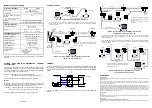
VOLTAGE DROP AND MAX DISTRIBUTED CURRENT
CALCULATIONS
For correct network management, the maximum number of readers which can
propagate power through the QLs must be calculated so that max distributed
current is not exceeded and so voltage drop doesn't affect reader functioning.
This is done according to the following formula:
Voltage Drop = (Max Reader Current x Number of readers) x
(Resistance per Meter per wire* x Cable length in Meters)
* the resistance calculation must include both wires (Vdc and GND).
Example:
An ID-NET™ network is composed of 4 DS2100N readers. Three 2 meter
ThinNet cables are used to connect the readers, which have Cable Resistance
= 0.058 Ohms per meter per wire. The network power is 24 Vdc.
(0.2083 A x 4 readers) x [(0.058 x 2) x 6 meters] = 0.58 Vdc voltage drop
24 Vdc - 0.58 = 23.42 Vdc at reader number 4 (worst case)
Integrate a sufficient number of QL200s to resupply network power.
821001640
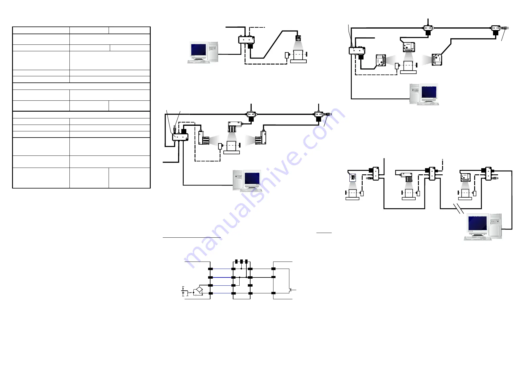
TYPICAL LAYOUTS
Point to Point - Matrix 200™ with QL500 (Ethernet to Host)
1
The reader must first be configured for Ethernet communication. This is done by connecting to the
reader through the RS232 Aux port available on the QL500 I/O Port and running the software
configuration program.
ID-NET™ Synchronized Network - Matrix 400™ Master with QL300
+ Matrix 400™ Slaves with QL150
TRIGGER
In order to allow direct trigger cabling between the photocell and the QL300/500 using standard
M12 A-coded one-to-one cables, the trigger signal has been internally wired to manage PNP
type photocells. The external trigger therefore
must be connected as shown in the diagram
below
.
EXT ERNAL TRIGGER
Ground
V
Signal
V
CC
~
~
+
-
READ ER
19
13
Vdc
I1B
QL300/500
2
1
+V
nc
19
13
Tr
ig
ge
r
18
I1A
4
I1+
18
7
GND
3
-V
7
Power
1
Vd
c
2
3
GN
D
R
ead
er
The electrical features of both inputs and outputs are given in the relative reader Reference
Manual.
ID-NET™ Synchronized Network - DS4800 Master with QL500
+ DS4800 Slaves with QL200 and QL100
1
The reader must first be configured for Ethernet communication. This is done by connecting to the
reader through the RS232 Aux port available on the QL500 I/O Port and running the software
configuration program.
2
The above diagram is an example showing layout connections and is not intended to represent power
limits, which instead, depend on each specific application. See "Voltage Drop and Max Distributed
Current Calculations".
ID-NET™ Multidata Network - DS4800 Master with QL300
+ Mixed Reader Slaves with QL300s
COMPLIANCE
FCC Compliance
Modifications or changes to this equipment without the expressed written approval of Datalogic could void the authority to
use the equipment.
This device complies with PART 15 of the FCC Rules. Operation is subject to the following two conditions: (1) This device
may not cause harmful interference, and (2) this device must accept any interference received, including interference
which may cause undesired operation.
This equipment has been tested and found to comply with the limits for a Class A digital device, pursuant to part 15 of the
FCC Rules. These limits are designed to provide reasonable protection against harmful interference when the equipment is
operated in a commercial environment. This equipment generates, uses, and can radiate radio frequency energy and, if not
installed and used in accordance with the instruction manual, may cause harmful interference to radio communications.
Operation of this equipment in a residential area is likely to cause harmful interference in which case the user will be
required to correct the interference at his own expense.
CE Compliance
Warning:
This is a Class A product. In a domestic environment this product may cause radio interference in which case the user may
be required to take adequate measures.
Power Supply
This product is intended to be installed by Qualified Personnel only.
This accessory device is intended to be supplied by a UL Listed or CSA Certified Power Unit with «Class 2» or LPS power
source.
Host
QL500
1
PS
Power
I/O
CAB-PW-EXT
Matrix 200™
Ethernet
Host
QL150
PS
Power
Main Interface
CBL-1490
ID-NET
Terminator
The ID-NET network must be terminated inserting an
ID-NET terminator into the QL300 (Master) and into the
last QL in the network.
Slave Nodes
CBL-1480-xx
CAB-PW-EXT
CBL-1480-xx
CAB-AUX03
CAB-AUX03
QL300
CBL-1496
ID-NET
Terminator
Master
QL150
ID-NET™
Host
QL200
2
PS
Power
Ethernet Interface
CBL-1490
ID-NET
Terminator
The ID-NET network must be terminated
inserting an ID-NET terminator into the last
QL in the network.
ID-NET on the QL500 is internally
terminated.
Slave Nodes
CBL-1480-xx
CAB-PW-EXT
CBL-1480-xx
Power
QL500
1
Master
QL100
ID-NET™
Host
QL300
PS
CBL-1490
ID-NET
Terminator
The ID-NET network must be terminated inserting an
ID-NET terminator into the QL300 (Master) and into the
last QL300 in the network.
Slave
CBL-1480-xx
AUX Port
CBL-1480-xx
Power
QL300
Master
QL300
Power
Power
Slave
PS
PS
CBL-1496
ID-NET
Terminator
ID-NET™


