QLM500 INSTALLATION MANUAL
8
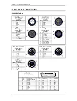
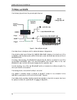
Pins 2 and 3 on the ID-NET connector carry the same power supply lines present on pins 1
and 3 of the PWR-IN connector; however power must only be supplied to the QLM500
through the PWR-IN connector.
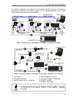
In an ID-NET™ network, the reading device connected to the QLM500
must
be configured
as an ID-NET™ Master; to facilitate the network setup, the QLM500 already provides an
internal bus termination resistor (the Master is the first device of the chain).
CAUTION
When using QLM500 in an ID-NET™ network application, the network
termination cap must be connected to the last device of the chain.
TRG CONNECTOR
TRG is a 4-pin Female A-Coded M12 connector. You can connect a
PNP
photocell to it,
which will act as an External Trigger (Input 1) for the connected reading device. Several
commercial cables are available to make this connection such as the SAC-4P-M12MS series
by Phoenix Contact.
When the Trigger is activated, the LED below the TRG connector is yellow.
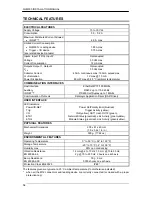
See the Technical Features table for electrical specifications.
NOTE
Pins 1 +V (I/O) and 3 -V (I/O) are derived from Vdc and GND and are
useful for supplying the external trigger through the QLM500 power source,
however pins 1 and 3 of the TRG connector must
not
be used as power
supply inputs to the QLM500.
I/O CONNECTOR
I/O is an 8-pin Female A-Coded M12 connector. It carries the signals for the additional I/O
(Input 2 / Secondary Trigger, Output 1 and Output 2) as shown below. If Input 2 is used as a
Secondary Trigger, the photocell must be a
PNP
device.
Note that all these signals are relative to the connected reader.
When the Input 2 (Secondary Trigger) is activated, the LED below the I/O connector is yellow.
When the Output 1 signal is activated, the LED below the I/O connector is red.
When the Output 2 signal is activated, the LED below the I/O connector is green.
See the Technical Features table for electrical specifications.
NOTE
Pins 1 +V (I/O) and 2 -V (I/O) are derived from Vdc and GND and are
useful for supplying the I/O devices through the QLM500 power source,
however pins 1 and 2 of the I/O connector must
not
be used as power
supply inputs to the QLM500.
NOTE
To reduce electromagnetic interference use a shielded cable for I/O
connections.


