INSTALLATION
9
2
Example
: The values in the table refer to a system composed of 1 active STAR-
Box™ and
N
passive STAR-Boxes™ with their STARGATE™ base
stations. All cable branches are
≤
50 m. long.
Supply Voltage
Consumption
Number of Devices (N)
12 V
350 mA
4
24 V
550 mA
8
30 V
650 mA
10
Alternatively, a system can adopt multiple power supply solutions. In this way,
STARGATE™ units can be powered separately from the STAR-Box™ network. See
par. 2.5.1 for jumper settings.
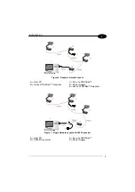
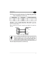
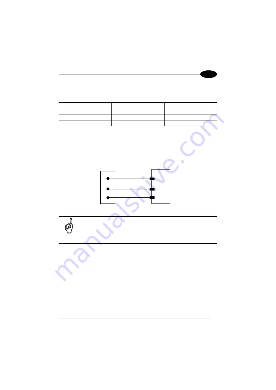
Power is supplied to the STAR-Box™ through the pins provided on the spring clamp
connector.
STAR-Box™
11
12
VS
GND
USER INTERFACE
GND
V+ (9 - 30 Vdc)
S3
13
SHIELD
Earth ground
Figure 8 - Power supply connections
NOTE
Pin 11 is electrically connected to pins 3 and 8, just as pin 12 is
electrically connected to pins 4 and 9 to allow power propagation
throughout the entire network. Pin 13 is electrically connected to pins
5 and 10 to allow the Shield to protect all network branches.
The
Shield should be connected to earth ground in one point only.
The power supply must be between 9 and 30 Vdc only.
Summary of Contents for STAR-Box
Page 1: ...STAR Box Installation Manual ...
Page 2: ......

