INSTALLATION
5
2
2.1.2 Electrical
Connections
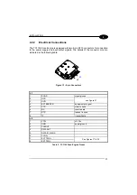
The TC1100 Scanner is equipped with a 25-pin female D-Sub connector for
connection to the power supply and input/output signals. The details of the connector
pins are indicated in the following table:
Figure 2 - 25-pin Female D-sub Connector
25-pin Connector
1 Shield
earth
ground
2 TX
transmit
data
3 RX
receive
data
4 RTS
request
to
send
5
CTS
clear to send
6 nc
not
connected
7 SGND
signal
ground
8
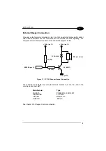
EXT BEEPER
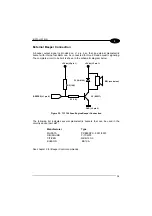
external beeper connection
9 VCC+
+5
Vdc
10 nc
not
connected
11 OUT+
12 OUT-
13 VCC+
+5
Vdc
14 nc
not
connected
15 nc
not
connected
16 nc
not
connected
17 nc
not
connected
18 EXT
TRIG+
19 EXT
TRIG-
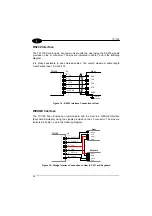
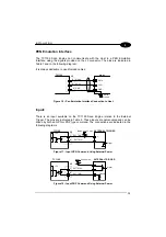
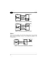
See Figures 6 to 9
20 DATAIN_WAND
21 DATAOUT
22 OUT-
23 CLKIN
24 CLKOUT
25 GND
power
ground
Table 1 - TC1100 Scanner Pinout
Summary of Contents for TC1100
Page 1: ...TC1100 Installation Manual ...
Page 2: ...TC1100 Reference Manual ...
Page 3: ...TC1100 REFERENCE MANUAL ...
Page 128: ...TC1100 120 A ...


