VLASE
TM
IR
18
2
2.2 DESCRIPTION OF THE MODULES
2.2.1 RESONATOR
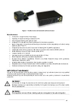
A description of the main parts of the resonator unit is provided here below:
Figure 11: Resonator view.
1) Scan Head signals connector
5) Fan connector
2) RF connector
6) Rack-Resonator connector
3) Optic fiber inlet
7) F-Theta scan lens
4) Cooling fan
Summary of Contents for VLASE IR 1PWX-TLS2
Page 1: ...USER S MANUAL VLASETM IR ...
Page 34: ...VLASETM IR 34 2 2 6 CONNECTION EXAMPLES Figure 27 Connection examples ...
Page 85: ...85 EXTERNAL LABEL PLACING Figure 67 Positioning of external labels rack ...
Page 86: ...86 Figure 68 Positioning of external labels resonator ...
Page 90: ...90 BLOCK DIAGRAM VLASETM SAFETY LOGIC DETAILS FOR AUTOMATIC PRODUCTION LINE ...
Page 108: ...108 APPENDIX G MECHANICAL DRAWINGS ...
Page 109: ...109 NOTE Please refer to Datalogic website for detailed drawings ...
Page 112: ......

