TECHNICAL SPECIFICATIONS
19
2
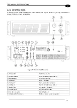
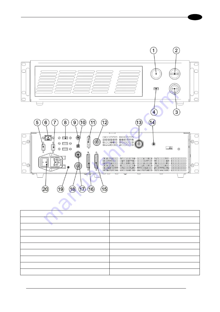
2.2.2 CONTROL RACK
A description of the control rack is provided here below for the purpose of obtaining the right information for
proper installation of the marking system.
Figure 12: Control rack front view.
1) Status LED
11) MDR connector
2) Enable selector
12) Resonator signals connector
3) Key selector
13) Optic fiber outlet
4) USB port
14) RF connector
5) VGA port
15) Command Box connector
6) LAN port
16) I/O connector (axis control)
7) RS232 port
17) Photocell connector
8) 3x USB ports
18) Encoder connector
9) Interlock connector
19) Earth ground
10) Interlock OUT connector
20) Mains power supply connection
Summary of Contents for VLASE IR 1PWX-TLS2
Page 1: ...USER S MANUAL VLASETM IR ...
Page 34: ...VLASETM IR 34 2 2 6 CONNECTION EXAMPLES Figure 27 Connection examples ...
Page 85: ...85 EXTERNAL LABEL PLACING Figure 67 Positioning of external labels rack ...
Page 86: ...86 Figure 68 Positioning of external labels resonator ...
Page 90: ...90 BLOCK DIAGRAM VLASETM SAFETY LOGIC DETAILS FOR AUTOMATIC PRODUCTION LINE ...
Page 108: ...108 APPENDIX G MECHANICAL DRAWINGS ...
Page 109: ...109 NOTE Please refer to Datalogic website for detailed drawings ...
Page 112: ......

