VLASE
TM
IR
22
2
2.4 CONNECTORS SPECIFICATIONS
2.4.1 INTERLOCK CONNECTOR
Interlock
disables
the Class4 laser source inside the marking system. Interlock internal circuit is designed to
comply with the single fault condition.
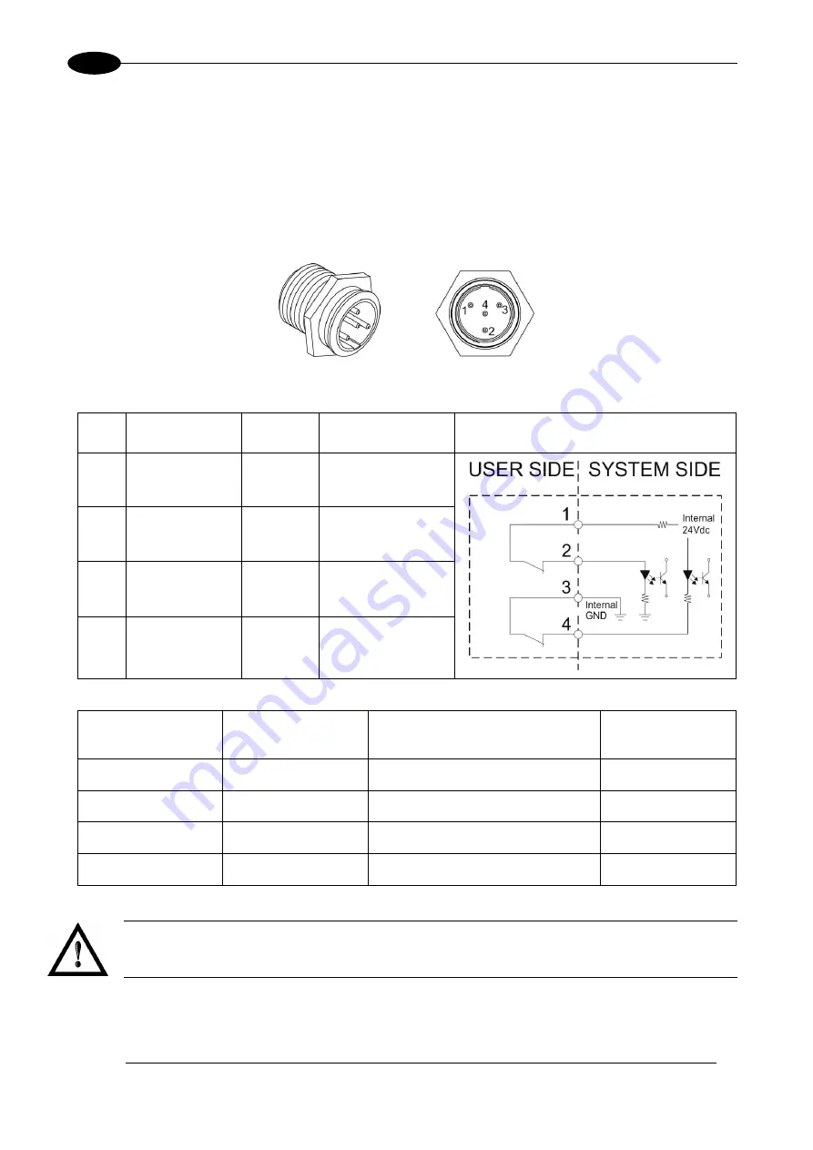
PANEL CONNECTOR
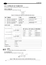
Type SWITCHCRAFT TB Series male Tini Q-G (Mini XLR) panel mount connector, 4 pins.
Figure 14: Male panel plug cod. TB4M (front view).
PIN SIGNAL
TYPE
DESCRIPTION
FUNCTIONAL DIAGRAM
1
VCC_INT_IN_A
OUTPUT
24V DC reference
for
INTERLOCK_A
signal
2
INTERLOCK_A
INPUT
INTERLOCK
IN
signal A
3
GND_INT_IN_B
GND
Ground reference
for
INTERLOCK_B
signal
4
INTERLOCK_B
INPUT
INTERLOCK
IN
signal B
PIN 1- PIN 2
PIN 3- PIN 4
MARKING FUNCTIONALITY CONDITION
CONTACT OPEN
CONTACT OPEN
NOT POSSIBLE
SAFE
CONTACT CLOSED
CONTACT OPEN
NOT POSSIBLE
DANGEROUS
CONTACT OPEN
CONTACT CLOSED
NOT POSSIBLE
DANGEROUS
CONTACT CLOSED
CONTACT CLOSED
POSSIBLE
DANGEROUS
WARNING!
In order to
NOT DAMAGE
the inter
lock circuitry, we recommend using “dry circuit” (zero voltage)
switches or relay circuitry.
Summary of Contents for VLASE IR 1PWX-TLS2
Page 1: ...USER S MANUAL VLASETM IR ...
Page 34: ...VLASETM IR 34 2 2 6 CONNECTION EXAMPLES Figure 27 Connection examples ...
Page 85: ...85 EXTERNAL LABEL PLACING Figure 67 Positioning of external labels rack ...
Page 86: ...86 Figure 68 Positioning of external labels resonator ...
Page 90: ...90 BLOCK DIAGRAM VLASETM SAFETY LOGIC DETAILS FOR AUTOMATIC PRODUCTION LINE ...
Page 108: ...108 APPENDIX G MECHANICAL DRAWINGS ...
Page 109: ...109 NOTE Please refer to Datalogic website for detailed drawings ...
Page 112: ......

