TECHNICAL SPECIFICATIONS
25
2
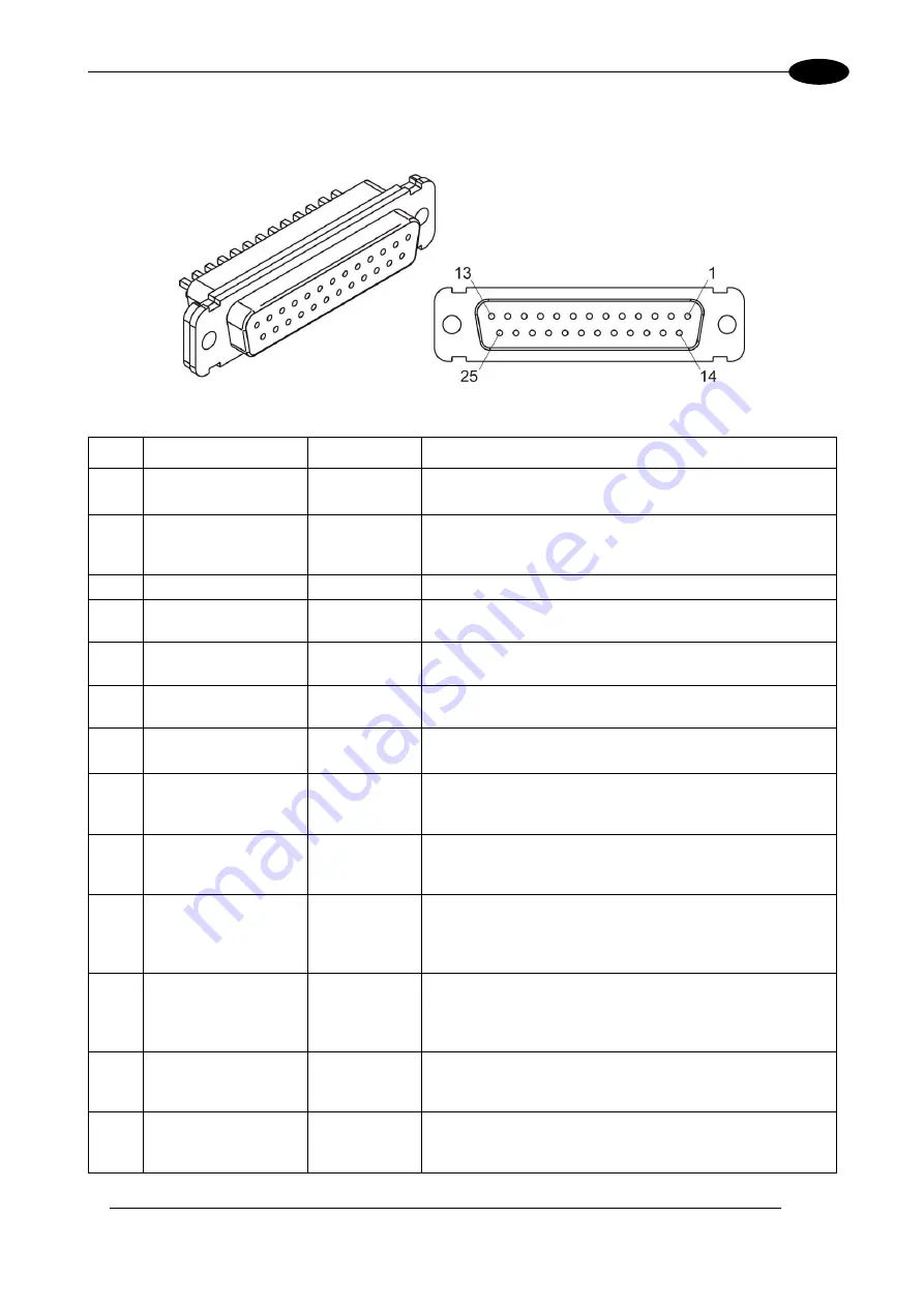
2.4.3 COMMAND BOX CONNECTOR (LASER CONTROL)
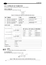
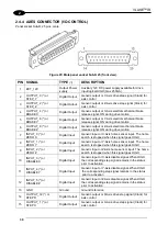
Panel socket Sub-D, 25 pins, female.
Figure 18: Female panel socket Sub-D 25 (front view).
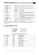
PIN SIGNAL
TYPE
(***)
DESCRIPTION
1
12V_ENABLE_B
Output power
supply
12V DC power supply available for
EXT_ENABLE_B
(max 250mA)
2
EXT_ENABLE_B
Digital Input
Secondary external
ENABLE
signal (see par. 2.4.3.1)
- HIGH level: contact closed
- LOW level or disconnected: contact opened
3
RESERVED
Digital Output
DO NOT CONNECT
4
EXT_12V
Output power
supply
Auxiliary 12V DC power supply available for drive input
logical HIGH (max 250mA)
5
EXT_12V
Output power
supply
Auxiliary 12V DC power supply available for drive input
logical HIGH (max 250mA)
6
EXT_12V
Output power
supply
Auxiliary 12V DC power supply available for drive input
logical HIGH (max 250mA)
7
12V_ENABLE_A
Output power
supply
12V DC power supply available for
EXT_ENABLE_A
(max 250mA)
8
EXT_ENABLE_A
Digital Input
Primary external
ENABLE
signal (see par. 2.4.3.1):
- HIGH level: contact closed;
- LOW level or disconnected: contact opened
9
BUSY (*)
Digital Output
This signal is used to know if the current spooler is
executing (marking in progress) (see par. 2.4.3.4):
- ON during marking process
10
CONNECTOR
PRESENCE
Digital Input
This signal is used to check the presence of the
Command Box connector (see paragraph 2.6):
- HIGH level: normal operation;
- LOW level or disconnected: laser source faulty
11
START MARKING
(*)
Digital Input
This signal is used to start to the marking process when a
document or a sequence is running in AUTO MODE (**)
or WORK MODE (**) (see paragraph 2.4.3.4):
- HIGH level pulsed signal start the marking process
12
EXT_KEY
Digital Input
External
KEY
signal (see paragraph 2.4.3.2):
- HIGH level: contact closed;
- LOW level or disconnected: contact opened
13
STOP MARKING (*)
Digital Input
This signal is used to stop the marking process (see
paragraph 2.4.3.4)
- HIGH level pulsed signal stop the marking process
Summary of Contents for VLASE IR 1PWX-TLS2
Page 1: ...USER S MANUAL VLASETM IR ...
Page 34: ...VLASETM IR 34 2 2 6 CONNECTION EXAMPLES Figure 27 Connection examples ...
Page 85: ...85 EXTERNAL LABEL PLACING Figure 67 Positioning of external labels rack ...
Page 86: ...86 Figure 68 Positioning of external labels resonator ...
Page 90: ...90 BLOCK DIAGRAM VLASETM SAFETY LOGIC DETAILS FOR AUTOMATIC PRODUCTION LINE ...
Page 108: ...108 APPENDIX G MECHANICAL DRAWINGS ...
Page 109: ...109 NOTE Please refer to Datalogic website for detailed drawings ...
Page 112: ......

