VLASE
TM
IR
30
2
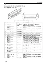
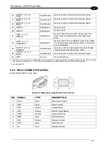
2.4.4 AXES CONNECTOR (I/O CONTROL)
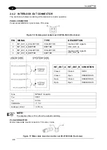
Panel socket Sub-D, 25 pins, male.
Figure 23: Male panel socket Sub-D 25 (front view).
PIN SIGNAL
TYPE
(**)
DESCRIPTION
1
EXT_12V
Output Power
supply
Auxiliary 12V DC power supply available for drive
input logical HIGH (max 250mA)
2
OUTPUT_0 (*) or
STEP_Y
Digital Output
Generic output or Y-Axis drive step signal (Clock) for
axis control
3
OUTPUT_2 (*) or
STEP_Z
Digital Output
Generic output or Z-Axis drive step signal (Clock) for
axis control
4
OUTPUT_4 (*) or
BRAKE X
Digital Output
Generic output or X-Axis electromechanical brake
release signal. ON during drive motion
5
OUTPUT_6 (*) or
BRAKE Y
Digital Output
Generic output or Y-Axis electromechanical brake
release signal. ON during drive motion
6
OUTPUT_8 (*) or
BRAKE Z
Digital Output
Generic output or Z-Axis electromechanical brake
release signal. ON during drive motion
7
INPUT_0 (*) or
ZERO X
Digital Input
Generic input or X-Axis home sensor input. The home
search is stopped when this signal goes HIGH
8
INPUT_1 (*) or
ZERO Y
Digital Input
Generic input or Y-Axis home sensor input. The home
search is stopped when this signal goes HIGH
9
INPUT_2 (*) or
ZERO Z
Digital Input
Generic input or Z-Axis home sensor input. The home
search is stopped when this signal goes HIGH
10
INPUT_3 (*) or
DISABLE X
Digital Input
Generic input or X-Axis disable signal. When HIGH,
the corresponding step signal remains in the status
prior to activation
11
INPUT_4 (*) or
DISABLE Y
Digital Input
Generic input or Y-Axis disable signal. When HIGH,
the corresponding step signal remains in the status
prior to activation
12
INPUT_5 (*) or
DISABLE Z
Digital Input
Generic input or Z-Axis disable signal. When HIGH,
the corresponding step signal remains in the status
prior to activation
13
GND
Ground
Ground reference
14
OUTPUT_12 (*) or
STEP R
Digital Output
Generic output or R-Axis drive step signal (Clock) for
axis control
15
OUTPUT_1 (*) or
STEP X
Digital Output
Generic output or X-Axis drive step signal (Clock) for
axis control
Summary of Contents for VLASE IR 1PWX-TLS2
Page 1: ...USER S MANUAL VLASETM IR ...
Page 34: ...VLASETM IR 34 2 2 6 CONNECTION EXAMPLES Figure 27 Connection examples ...
Page 85: ...85 EXTERNAL LABEL PLACING Figure 67 Positioning of external labels rack ...
Page 86: ...86 Figure 68 Positioning of external labels resonator ...
Page 90: ...90 BLOCK DIAGRAM VLASETM SAFETY LOGIC DETAILS FOR AUTOMATIC PRODUCTION LINE ...
Page 108: ...108 APPENDIX G MECHANICAL DRAWINGS ...
Page 109: ...109 NOTE Please refer to Datalogic website for detailed drawings ...
Page 112: ......

