background image

COMPONENT SPECIFICATION 


C00525

C00525

C00525

C00525    


- 2 - 

1. DESCRIPTION OF CONNECTOR AND INTENDED APPLICATION 

A range of 2mm pitch male and female rectangular, fully shrouded unsealed connectors with replaceable 
contacts for interconnecting board to board, cable to board and cable to cable.  The range covers 2 to 50 
ways, in various application methods.  Female connectors are available for crimp, vertical through-board and 
surface mount termination.  Male connectors are available for crimp, vertical or horizontal (90°) through-
board and vertical surface-mount termination.  Overmoulding of cable assemblies is also available for crimp 
versions. 

The connectors are provided with a range of contact terminations (as shown in Appendix 1) that are gold or 
gold/tin plated.  The contact zone of a gold plated contact is hard acid gold of 98% purity. 

The connector is intended for use as a low voltage connector in high packing density electronic equipment.  
The connector is polarised to prevent mis-matching and can be produced with a latching feature (L-Tek) or in 
a jackscrew (J-Tek) format, with or without board mounting. 

L-Tek and J-Tek connectors are available with low-frequency (LF) contacts, while customised Mixed 
Technology (Mix-Tek) connectors are also available with jackscrews, with a choice of power or coax contacts. 

NOTE: Some connector styles are available manufactured and tested to BS9525 F0033. All other connectors in 
the range are designed to the same specification. 

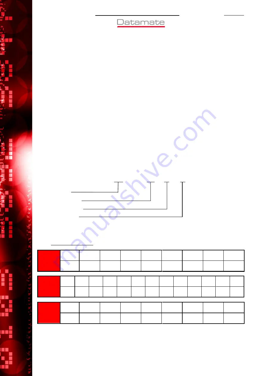
2. MARKING OF THE CONNECTOR AND/OR PACKAGE [ORDER CODE] 

The marking (order code) shall appear on the package and shall be as follows: 


2.1.  ORDER CODE: 


M80 

XXX 

XX 

XX 


Series No. 

Connector Style 

Number of Ways 

Contact Finish 


For details of styles, as well as Mix-Tek and M83 markings and styles see the latest catalogue, or 
individual drawings. 


2.1.1. Number of ways: 


SINGLE 

ROW 

(standard)


No. of 

ways 

17 

22 

Order 

Code 

02 

03 

04 

05 

06 

07 

17 

22 


DOUBLE 

ROW 

(standard)


No. of 

ways 

2+2 

3+3 

4+4 

5+5 

6+6 

7+7 

8+8 

9+9 

10+10  13+13  17+17  22+22 

Order 

Code 

04 

06 

08 

10 

12 

14 

16 

18 

20 

26 

34 

44 


DOUBLE 

ROW 

(jackscrew)


No. of 

ways 

3+3 

5+5 

7+7 

10+10 

13+13 

17+17 

21+21 

25+25 

Order 

Code 

06 

10 

14 

20 

26 

34 

42 

50 

Summary of Contents for M80 Series

Page 1: ... TITLE PAGE 1 Description of Connectors and Intended Applications 2 2 Marking of Connector and or Package 2 3 Ratings 3 Appendix 1 Contact Orientations 7 Appendix 2 Coax Contact Details 10 Appendix 3 Gauges Low Frequency 12 Appendix 4 Test for Latch Integrity 13 Appendix 5 Instructions for the use of connectors fitted with Jackscrews 14 Appendix 6 Instructions for the use of Jackscrews 15 ...

Page 2: ...revent mis matching and can be produced with a latching feature L Tek or in a jackscrew J Tek format with or without board mounting L Tek and J Tek connectors are available with low frequency LF contacts while customised Mixed Technology Mix Tek connectors are also available with jackscrews with a choice of power or coax contacts NOTE Some connector styles are available manufactured and tested to ...

Page 3: ...stance after conditioning 25mΩ max Insulation resistance initial 1 000 MΩ min Insulation resistance hot after conditioning 100 MΩ min Creepage path contact to contact 0 35mm min Air gap contact to contact 0 35mm min 3 1 2 Environmental characteristics Environmental classification 55 125 56 Days at 95 RH Low air pressure severity when only one contact is electrically loaded 300 mbar 9 144M 30 000ft...

Page 4: ...ing pin no latch fitted 0 2N min M83 insertion force per contact using mating pin no latch fitted 1 0N max M83 withdrawal force per contact using mating pin no latch fitted 0 2N min 3 1 4 Wire Termination Range Wire type recommended BS 3G 210 Type A Extra small bore crimp contact details Crimp type Crimp type Crimp type Crimp type Extra small bore Extra small bore Extra small bore Extra small bore...

Page 5: ...characteristics Durability 500 operations Insertion force 8 0N max Withdrawal force 0 5N min Contact wipe 1 30mm min Contact replacement in moulding 5 times max 3 3 POWER CONTACTS 3 3 1 Electrical characteristics Current rating M80 3XX contact only 20A max Current rating M80 PXX contact only 40A max Working Voltage at 1013mbar sea level 800V DC or AC Peak Voltage Proof at 1013mbar sea level 1200V ...

Page 6: ...ce M80 PXX contacts 15 0N max Withdrawal force 0 5N min Contact wipe 1 30mm min Contact replacement in moulding 5 times max 3 4 SOLDERING DATA Solderability for PC Tail SMT product 245 C for 5 seconds Soldering heat resistance for SMT products only 260 C for 10 seconds ...

Page 7: ...ooking onto the contact face A1 1 SINGLE ROW 2 1 3 1 4 1 5 1 6 1 7 1 17 1 22 1 2 way 22 way 17 way 7 way 6 way 5 way 4 way 3 way 90 tail typical Polarising Key A1 2 DOUBLE ROW 34 way 26 way 20 way 18 way 16 way 14 way 12 way 10 way 9 1 4 6 1 10 5 5 1 8 4 4 6 1 3 3 1 16 8 8 1 14 7 7 1 12 6 14 26 11 20 1 13 1 10 10 1 18 9 2 23 44 1 22 18 34 1 17 44 way 8 way 6 way 4 way Polarising Key 90 tail typica...

Page 8: ...g onto the contact face A1 3 M80 DOUBLE ROW 3 20 11 17 34 18 1 26 14 21 42 22 13 1 14 8 5 6 10 1 4 6 10 26 50 1 25 1 1 1 7 1 Polarising Key 90 tail typical 6 way 50 way 42 way 10 way 14 way 20 way 26 way 34 way A1 4 M80 DOUBLE ROW 1 7 6 12 C A D C 1 4 5 8 B A A F 90 tail typical Polarising Key Non symmetrical e g 3 special 12 signal Symmetrical e g 2 special 8 signal 2 special Special contacts onl...

Page 9: ...CT ORIENTATIONS continued These diagrams show pin numbers with reference to the polarisation feature They represent male connectors shown looking onto the contact face A1 5 M83 3 ROW A1 6 M83 3 ROW 1 6 13 18 1 8 A B C D All signal contacts only Signal and special contacts ...

Page 10: ... of coax connector to be assembled 3 Slide sleeve onto cable past stripped area 4 Crimp contact to end of cable inner conductor 5 Insert cable and contact into coax body from back end make sure that the braid goes outside and over the end section 6 Slide sleeve back over the end of the coax body and the braid Crimp into place on the cable insulation using a hexagonal crimping tool Inner Conductor ...

Page 11: ...ar as it will go The cable inner conductor will be visible through the hole in the top of the coax body and should go into the slot in the inner contact of the body Make sure that the braid goes outside and over the end section 5 Solder the cable inner conductor to the body inner contact When cool place the insulator inside the top and press the cover into place Slide the sleeve up to meet the coa...

Page 12: ...limit of 0 005mm is allowable on gauging diameters 5 Loading force Bending moment to give 0 002Nm Test prod only 6 All dimensions are in millimetres 7 For explanation of dimensions etc see BS8888 8 Unless otherwise stated all dimensions are maxima A3 1 TEST PROD 0 2 LAP Spherical rad R 3 16 2 70 2 65 9 40 9 27 2 362 2 350 Ø 0 500 0 495 Ø A3 2 SIZING GAUGE Spherical rad 0 2 LAP 6 25 6 15 0 505 0 50...

Page 13: ... 00 22 00 28 00 36 00 46 00 Dim B 0 02 0 00 5 00 7 00 9 00 11 00 13 00 15 00 17 00 19 00 21 00 27 00 35 00 45 00 A4 2 LATCH INTEGRITY TEST B A B A Figure 1 Figure 2 Figure 3 When Gauge A is placed between the two faces of the latch clips as shown in Figure 1 the connector shall be held against its own weight When Gauge B is placed between the two faces of the latch clips as shown in Figure 2 the c...

Page 14: ...rect polarity lightly push home the floating half until the jackscrews touch Then maintaining the pressure turn one of the floating jackscrews clockwise until it engages with the fixed screw Repeat with the other screw Then screw in each jackscrew ensuring even loading by applying a maximum of one turn to each screw in sequence until the connector is bottomed This will be evident by a sudden incre...

Page 15: ...her Once the connectors are mated use a screwdriver to push down onto each 101Lok Jackscrew until the spring is compressed Turn the Jackscrew 101 degreess and release The Jackscrew should remain partially compressed 3 To disengage use a screwdriver to push down on each 101Lok Jackscrew until the spring is compressed Turn the Jackscrew anti clockwise 101 degrees and release The Jackscrew will sprin...

Reviews: