COMPONENT SPECIFICATION
C00525
C00525
C00525
C00525
- 8 -
APPENDIX 1 – CONTACT ORIENTATIONS (continued)
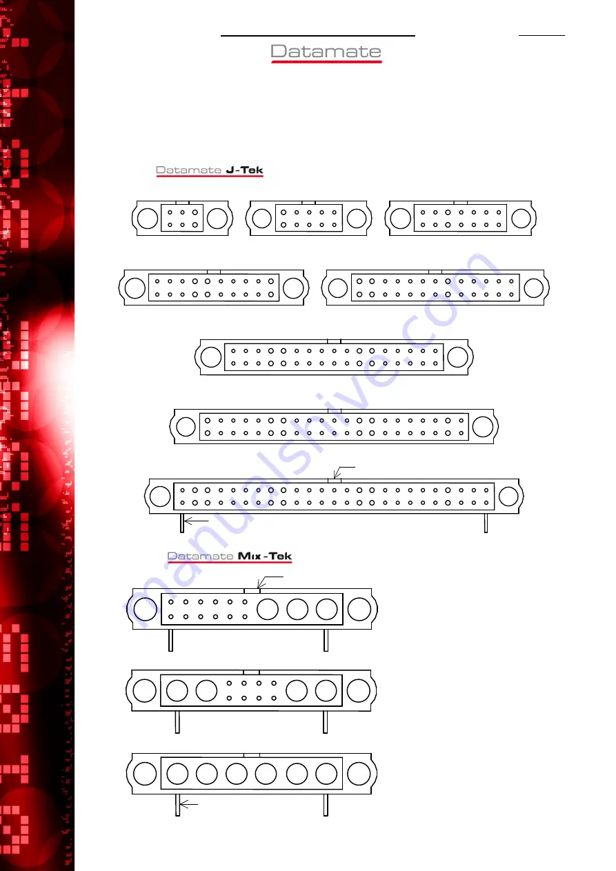
These diagrams show pin numbers with reference to the polarisation feature. They represent male
connectors, shown looking onto the contact face.
A1.3. M80 DOUBLE ROW
3
20
11
17
34
18
1
26
14
21
42
22
13
1
14
8
5
6
10
1
4
6
10
26
50
1
25
1
1
1
7
1
Polarising Key
90° tail (typical)
6-way
50-way
42-way
10-way
14-way
20-way
26-way
34-way
A1.4. M80 DOUBLE ROW
1
7
6
12
C
A
D
C
1
4
5
8
B
A
A
F
90° tail (typical)
Polarising Key
Non-symmetrical
(e.g. 3 special, 12 signal)
Symmetrical
(e.g. 2 special, 8 signal, 2 special)
Special contacts only
(e.g. 6 special)


