background image


94


A-Class


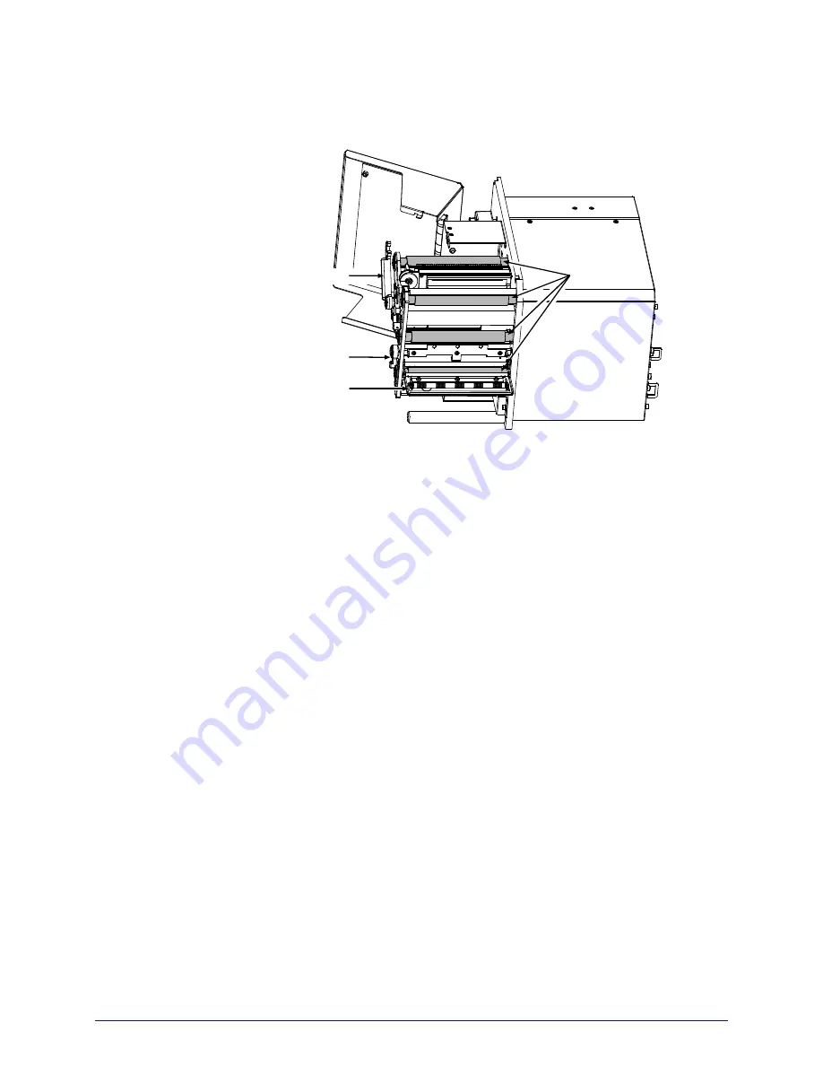
2.  Raise the Head Lift Lever. Lower the Peel Assembly Release Lever. Remove media and 

ribbon. 


Rollers

Peel Assembly

Peel Assembly Release Lever

Head Lift Lever


3.  Using a cotton swab dampened with isopropyl alcohol, clean the Rollers, rotating each as 

necessary to clean its entire surface.  


4.  After allowing the Rollers to dry, replace ribbon and media. Close the Peel Assembly and 

lower the Head Lift Lever into the locked position.   


5.  Close the access cover. Plug in and turn ON the printer. This completes the procedure.  


5.5.3  Cleaning the Peel Assembly 


Clean the Peel Assembly as follows: 


1.  Turn OFF and unplug the printer. Raise the access cover. 


2.  Raise the Head Lift Lever. Lower the Peel Assembly Release Lever. Remove media and 

ribbon. 

Summary of Contents for A-Class A-4212

Page 1: ...Operator s Manual ...

Page 2: ......

Page 3: ...ny other person or party to duplicate or copy the Firmware or the information contained in the non volatile or programmable memory The firmware Software is protected by applicable copyright laws and Licensor retains all rights not expressly granted In no event will Licensor or its suppliers be liable for any damages or loss including direct incidental economic special or consequential damages aris...

Page 4: ...ares under sole responsibility that this product conforms to the following standards or other normative documents EMC EN 55022 1993 Class B EN 50024 1998 Safety This product complies with the requirements of EN 60950 1 First Edition FCC This device complies with FCC CFR 47 Part 15 Class A Note This equipment has been tested and found to comply with the limits for a Class A digital device pursuant ...

Page 5: ......

Page 6: ......

Page 7: ...ction labels on the print engine Mount the print engine securely in the applicator system Do not place the print engine on or near a heat source To protect from overheating make sure no openings on the print engine are blocked Never insert anything into the ventilation slots and openings of the print engine Do not use the print engine near water or spill liquid into it Ensure that the AC power sou...

Page 8: ......

Page 9: ...tarted 9 2 1 Unpacking 9 2 1 1 Contents 10 2 1 2 Additional Requirements 10 2 2 Installation 10 2 2 1 Mounting Requirements 10 2 2 2 Interfacing a Host 14 2 2 2 1 Parallel Port Connections 15 2 2 2 2 Serial Port Connections 15 2 2 2 3 USB Port Connections 18 2 2 3 Connecting an Applicator 19 2 2 4 Connecting Power 19 3 Setting up the Printer 21 3 1 Loading Media 21 3 2 Adjusting the Media Sensor 2...

Page 10: ...ut 31 4 1 1 Ready Mode 32 4 2 The System Menu 33 4 2 1 Media Settings 35 4 2 2 Print Control 37 4 2 3 Printer Options 39 4 2 4 System Settings 45 4 2 5 Communications 54 4 2 6 Diagnostics 63 4 2 7 MCL Options 65 4 3 The Test Menu 66 4 3 1 Print Quality Label 68 4 3 2 Print Configuration 68 4 3 3 Ribbon Test Label 69 4 3 4 Validation Label 69 4 3 5 Print Last Label 69 4 3 6 User Defined Label 69 ...

Page 11: ...3 2 Burn Line Adjustment 85 5 4 Printhead Replacement 86 5 5 Maintenance Schedule 90 5 5 1 Cleaning the Printhead 91 5 5 2 Cleaning the Rollers 93 5 5 3 Cleaning the Peel Assembly 94 5 5 4 Cleaning the Media Sensor Media Path and Peel Bar 96 5 5 5 Cleaning Exterior Surfaces 97 5 6 Reset Methods 97 5 6 1 Soft Reset 97 5 6 2 Level One Reset 97 5 6 3 Level Two Reset 97 5 7 Updating the Firmware 98 5 ...

Page 12: ...ved Media and Ribbon 120 Appendix A 123 Module Assignments 123 File Handling Messages 123 Cut Behind Setup 125 Appendix B 127 Print Resolutions and Widths 127 Speed Ranges 127 Column Row Emulation Ranges 128 Custom Adjustments Column Present Row Adjust Ranges 128 Appendix C 129 PE Peel Bar Location 129 PE to A Class GPIO Adapter Cable 129 Appendix D 131 Applicator Interface Overview 131 Appendix E...

Page 13: ...v Multi Language Menu 139 Appendix F 143 Saving a Configuration File 143 Appendix G 145 Ribbon Saver Overview 145 Warranty Information 147 Glossary 149 ...

Page 14: ...vi ...

Page 15: ...l the information necessary for installation setup and operation of the printer To begin printing refer to the instructions provided with your label creation software or to write custom label programs reference the Class Series 2 Programmer s Manual on the Accessories CD ROM also available at http www datamaxcorp com The printer s model number located on the Serial Tag affixed to the inside of the...

Page 16: ...ay languages Industry standard bar code symbologies Time stamp at print capability with time and date battery back up Static brushes Printhead resistance verification Configurable fault handling capability with reprint and void selections Parse error tolerant command language interpretation Internal test labels for verification validation and configuration Multiple setup restore capability Paper r...

Page 17: ...ble font Linerless Cutter A mechanism specifically designed to cut linerless media after printing MCL A software tool suite for information collection applications allowing input data from peripheral devices scanners weigh scales keyboards etc without the need of a host computer Remote Control Panel A hardwired assembly allowing remote operation six feet 1 8 m maximum distance RFID A Radio Frequen...

Page 18: ...ce Level Option Installer DMXNetII DMX Certified Technician DMXrfNetII DMX Certified Technician Expanded Flash Main Logic CCA DMX Certified Technician Linerless Cutter DMX Certified Technician MCL DMX Certified Technician Remote Display DMX Certified Technician RFID Built Factory Only RFID Ready DMX Certified Technician Ribbon Saver Factory Only Thermal Transfer DMX Certified Technician Twinax Coa...

Page 19: ...Serial Port 7 USB Port 8 Parallel Port 9 GPI O Port B 10 Ribbon Take Up Hub 11 Ribbon Supply Hub 12 Upper Media Post 13 Lower Media Post 14 Cover Sensor 15 Upper Ribbon Idler 16 Leveling Cam 17 Printhead Assembly 18 Peel Bar 19 Platen Roller 20 Head Lift Lever 21 Media Sensor 22 Media Sensor Adjustment Knob 23 Media Guide 24 Peel Assembly Release Lever 25 Locking Post 26 Peel Assembly 27 COM D 28 ...

Page 20: ...6 A Class 1 2 1 Right Hand Models 1 2 3 4 6 7 8 9 5 27 28 15 16 17 18 19 14 20 21 10 11 12 13 3 22 23 24 25 26 ...

Page 21: ...A Class 7 1 2 2 Left Hand Models 1 2 3 6 7 8 9 5 4 27 28 15 16 17 18 19 14 20 21 10 11 12 13 22 23 24 25 26 ...

Page 22: ...8 A Class ...

Page 23: ...kaging material 1 With the Shipping Carton arrows pointing upward open the Shipping Carton and remove the Accessories Box and the Top Foams 2 Carefully lift the wrapped Printer from the carton and place it on a solid level surface Accessories Box Printer Shipping Carton Top Foam Bottom Foam Top Foam Bottom Foam 3 Remove the Printer from the plastic bag and then remove all remaining packing materia...

Page 24: ...dows Drivers and basic labeling software 2 2 Installation Before installing the printer ensure that the environmental conditions of the site fall within the range specified in Section 7 and always avoid the following environments Do not place the printer in direct sunlight or near a heat source and Do not place the printer where it will be exposed to liquids or excessive dust or dirt 2 2 1 Mountin...

Page 25: ...Class 11 Attach the printer to the support structure using a 10 screw inserted at each Mounting Hole position see note below Mounting Holes The following drawings detail additional mounting considerations ...

Page 26: ...12 A Class A 4xxx models Front View Peel Assembly lowered 9 67 246mm 11 81 300mm 2 25 57mm Side View 10 45 266mm 7 68 195mm 15 35 390mm Side View Cover raised 7 66 195mm 12 51 318mm 20 17 512mm ...

Page 27: ...A Class 13 A 6xxx models Front View Peel Assembly lowered 9 67 246mm 11 81 300mm 2 25 57mm Side View 9 68 246mm 17 35 441mm 10 45 266mm Side View Cover raised 14 51 369mm 7 66 195mm 22 17 563mm ...

Page 28: ... power up or after a period of inactivity interface port selection occurs automatically upon detection of valid data If the incoming data flow stops and the Host Timeout period see Section 4 2 5 is achieved partially received formats will be ignored and the port detection process repeated The location of the following connections can vary by printer model and host hardware configuration To change ...

Page 29: ...5 communications COM C and COM D support RS 232 see Appendix D for exceptions Pin outs are given below The port baud rate word length parity stop bits and protocol must be configured to match the host s settings see Section 4 2 5 Port A and COM C J4 Port A only COM D J3 Pin Number RS 232 Function RS 422 RS 485 Function RS 232 Function 1 5V 5 amps 5V 5 amps 2 RX RXD RTS 3 TX TXD Ground 4 DTR RXD TX...

Page 30: ... To use RS 422 485 communications Port A only the main logic card must be reconfigured Always wear a wrist strap and follow standard ESD prevention measures when handling the Main Logic Card 1 Turn OFF the power switch unplug the AC Power Cord from the printer and remove any interface cable s already attached to the Main Logic Card 2 Remove the two Screws securing the Main Logic Card to the printe...

Page 31: ... pins 1 2 and place them across pins 2 3 respectively JMP 1 JMP 2 JMP 3 JMP 4 JMP 5 JMP 6 4 Replace the Main Logic Card and secure it using the previously removed screws 5 Connect an RS 422 485 interface cable to Serial Port A see the pin out table above 6 Plug in and turn ON the printer Configure the port communication settings to match that of the host COM D Port Connections 10101010 ...

Page 32: ...GROUND DTR DSR CTS CTS DTR RTS 2 7 8 4 5 3 1 2 3 4 5 6 8 7 9 NC 6 NC NC Part 32 2603 00 2 2 2 3 USB Port Connections The Universal Serial Bus port requires a standard USB cable This USB Port is a device end only connection Never attach a keyboard mouse modem etc to this port damage can result ...

Page 33: ...PIO Port s may result in damage to the printer and or the applicator If upgrading a PE to A Class GPIO conversion cable is available see Appendix C 2 2 4 Connecting Power The power cord connects to the AC receptacle on back of the printer Make the connection and power up the printer as follows 1 Ensure that AC power to the host computer and applicator system are OFF 2 Ensure that the printer s Pow...

Page 34: ...20 A Class Power Switch 3 Connect the AC Power Cord to the printer and then to a properly grounded outlet 4 Turn ON in the following order the host computer the applicator system and then the printer ...

Page 35: ...ead Lift Lever 2 Route the Media between the Media Posts through the Media Sensor over the Peel Bar and out of the printer as shown below Media Head Lift Lever Media Posts Media Sensor Access Cover 3 To peel die cut labels after printing press down on the Peel Assembly Release Lever to lower the Peel Assembly otherwise proceed directly to Step 6 ...

Page 36: ...bly Release Lever Peel Assembly 4 Remove the labels from 12 inches 30 cm of the Media Liner Route the Media Liner down to the Peel Assembly over the Latch Roller and through the Slot as shown below Media Peel Assembly Media Liner ...

Page 37: ...ly Latch Roller Slot 5 Pull the Media Liner through the Slot in the Peel Assembly until all slack is removed Lifting from the center raise the Peel Assembly until it locks into place Head Lift Lever Peel Assembly Media Guide ...

Page 38: ...on thermal transfer media load ribbon see Section 3 3 otherwise go to Step 9 9 Lower the Head Lift Lever until it is completely and securely engaged onto the Locking Post 10 If loading media for the first time or if changing to a different media type or size press and hold the FEED Key until at least two labels have been output see Section 3 4 11 Adjust the Leveling Cam see Section 5 3 1 ...

Page 39: ...the type of media being used rotate the Media Sensor Adjustment Knob until the Eye Mark on the Media Sensor is positioned according to the table below Media Sensor Adjustment and Type Required Media Type Eye Mark Position Sensor Type Required Die cut Centered over the label Notched Centered over the notch Gap Reflective Centered over the black mark Reflective Continuous Near the middle of the medi...

Page 40: ... is recommended for added protection against abrasive wear 3 3 1 Right Hand Models Load ribbon as follows 1 Orient the unwind position of the Ribbon according to the coated side CSI or CSO and then slide the Ribbon Roll completely onto the Ribbon Supply Hub as shown below CSO Ribbon Roll Ribbon Ribbon Supply Hub Ribbon Ribbon Supply Hub CSI Ribbon Roll CSO Ribbon CSI Ribbon ...

Page 41: ...ake Up Hub 3 Rotate the Ribbon Take Up Hub clockwise several times to secure the Ribbon 4 Lower and lock the Head Lift Lever then close the access cover CSO Ribbon Roll Ribbon Ribbon Take Up Hub Upper Idler Ribbon Shield Lower Idler Head Lift Lever Ribbon CSI Ribbon Roll Ribbon Take Up Hub Upper Idler Ribbon Shield Head Lift Lever Lower Idler CSO Ribbon CSI Ribbon ...

Page 42: ... Ribbon Supply Hub as shown below CSO Ribbon Roll Ribbon Supply Hub Ribbon CSI Ribbon Roll Ribbon Supply Hub Ribbon CSO Ribbon CSI Ribbon 2 With the Head Lift Lever raised route the Ribbon under the Lower Idler over the Ribbon Shield and Upper Idler and then counterclockwise around to the Ribbon Take Up Hub 3 Rotate the Ribbon Take Up Hub counterclockwise several times to secure the Ribbon ...

Page 43: ...ibbon Shield Head Lift Lever CSO Ribbon CSI Ribbon 3 3 3 Removing Ribbon After the ribbon supply has been exhausted grasp the used ribbon and while squeezing pull to collapse the Ribbon Take Up Hub then slip off the ribbon Next slip off the empty core from the Ribbon Supply Hub If using a narrow width ribbon it may be necessary to use one hand to pull and collapse the Ribbon Take Up Hub while usin...

Page 44: ... liner If CANNOT CALIBRATE is displayed try calibrating over a longer distance Press and hold the FEED Key until the printer has output three or more labels If this method also fails that is if UNCALIBRATED is displayed perform the Standard Calibration see Section 5 2 1 3 5 Print Quality Controls Flexible printing controls are provided Of these the amount of heat applied and the rate of media move...

Page 45: ...USED Display Item Function Current State Indicators COMM indicates data is being received and processed and PAUSE indicates the printer is in a paused condition Time Date Provides the current Time and Date setting Printer Status Provides the READY message a label counter when batch printing and any prompt condition warning or fault message Display Window Provides several types of function informat...

Page 46: ...nt State Indicators Pressing the key again will return normal operation FEED The FEED Key advances one label and clears any corrected faults Also pressing and holding this key causes calibration see Section 3 4 CANCEL The CANCEL Key pauses operation and then prompts you for confirmation If yes the current job is cancelled and the printer remains paused Also pressing and holding this key resets the...

Page 47: ...e Section 4 3 When shaded this denotes that security is enabled and that a password must be entered to proceed see Section 4 2 4 Also pressing and holding this key evokes the printhead cleaning routine for use with Cleaning Cards or Cleaning Film see Section 5 5 1 The DOWN ARROW Key selects the next Menu Branch Also in some submenus this scrolls alphanumeric characters for filenames Not all branch...

Page 48: ...Section 4 2 4 Prompts may require confirmation before menu or printing changes are accepted see Section 5 1 1 Host computer commands may in some cases override menu settings see Section 4 2 5 Depending upon the firmware and options some of the menu selections represented below may not appear in your printer and may indicate NOT INSTALLED when accessed Symbols are used in the following menu listing...

Page 49: ...the label when the SENSOR TYPE is set to CONTINUOUS where 04 00in 0 99 99 Is the desired length of the format MAXIMUM LABEL LENGTH Sets the distance that the printer will feed GAP or REFLECTIVE media before declaring a TOF fault where 16 00in 0 99 99 Is the length of travel to detect a TOF gap or mark This distance should be 2 5 to 3 times the length of the label PAPER OUT DISTANCE Sets the distan...

Page 50: ...s the calibration process establishing sensor values based on sampled readings see Section 5 2 1 ADVANCED ENTRY Sets the sensor values based on an extended manual sampling process see Section 5 2 2 where SENSOR LEVELS 170 0 255 Establishes the threshold SENSOR GAIN 13 0 31 Establishes the sensitivity PRINTHEAD CLEANING Controls printhead cleaning alerts and functions where CLEAN HEAD SCHEDULE 000 ...

Page 51: ... rate of label movement during printing where XX Xin sec X XX Is the speed setting see Appendix B for the model dependant default and range Slower speeds may be required to print detailed images while faster printing may require an increased HEAT setting for sufficient energy transfer FEED SPEED Controls the rate of label movement between printing areas where XX Xin sec X XX Is the speed setting s...

Page 52: ...ing any print data that extends past this mark CUSTOM ADJUSTMENTS These selections independently change the listed parameters allowing slight mechanical compensations sometimes evident when multiple printers share label formats or for special printer specific formatting adjustments where DARKNESS 32 1 64 Controls the printhead strobe time see HEAT above to fine tune the solid areas of an image CON...

Page 53: ...laims all storage space associated with the deleted files on the specified module CUTTER Controls the Cutter and queuing functions where MODE Sets the detection method and printer response where AUTO The presence of the cutter is automatically sensed If detected the cutter is enabled otherwise it will be ignored ENABLED Enables the cutter If the cutter is not detected a fault will be generated DIS...

Page 54: ...ption where MODE Sets the detection method and response of the printer where DISABLED Disables the option AUTO Detects and enables the scanner if not detected the option will be ignored ENABLED Enables the scanner if not detected a fault will be generated BARCODES Specifies the bar code type s for scanning where Enabling only the types to be checked helps maximize throughput CODE 39 IATA CODABAR I...

Page 55: ... of requires 25 inches of the bar code height be 100 readable The specified distance should not exceed 50 of the measured bar code height REDUNDANCY LEVEL Ensures bar code integrity by specifying a consecutive number of identical decodes where READ BARCODE 2X 1X 6X Sets the read count e g a 3X setting requires three identical decodes to pass High redundancy rates and fast print speeds may cause er...

Page 56: ...ec overlap of Data Ready DRDY and End of Print EOP DRDY signal end inhibits FEED and De asserts DRDY upon PAUSE or FAULT BARCODE VERIFIER Enables the parameters for bar code verifier functions START OF PRINT Selects the type of input signal required to initiate printing where LOW PULSE Triggers printing with a low pulse HIGH PULSE Triggers printing with a high pulse ACTIVE LOW Triggers printing wi...

Page 57: ...ers slew with a low signal LOW PULSE Triggers slew with a low pulse HIGH PULSE Triggers slew with a high pulse ACTIVE LOW Triggers slew with a low signal ACTIVE HIGH Triggers slew with a high signal ERR ON PAUSE APP2 Sets the output Applicator Interface Card Type 2 equipped only when a service required fault occurs where ENABLE Enables the output signal DISABLE Disables the output signal RFID Cont...

Page 58: ... to permanently deactivate the tag where 00 00 00 00 Is the code in the form B3 B2 B1 B0 ACCESS CODE Sets the code to protect tag memory contents where 00 00 00 00 Is the code in the form B3 B2 B1 B0 GEN 2 LOCK ACTION Sets the lock for Gen 2 tags where NONE Does not lock the tag PERMALOCK Locks data permanently PWD READ WRITE Locks data with password protection for writing data BOTH Allows both Pe...

Page 59: ...ocess CALIBRATING RFID will be displayed as media is scanned for the tag location and power followed by TOF positioning and the results where if successful the database parameters will be updated NO No calibration occurs SET DEFAULTS Allows the RFID settings to be restored to the factory values where YES Returns the RFID settings to default values NO Retains the current settings 4 2 4 System Setti...

Page 60: ...ified where D Is the module see Appendix A for availability SCALEABLE FONT CACHE Configures the number of 1KB memory blocks for the scaleable font engine where 0312 XXX XXXX KB Is the memory allocation see Appendix A for availability SINGLE BYTE SYMBOLS Sets the code page used for single byte fonts where PC_850 MULTILINGUAL Is the selected code page See the Class Series 2 Programmer s Manual for d...

Page 61: ... Prints the current database information see Section 4 3 2 CONFIGURATION LEVEL Displays the hardware and software levels of the printer where This data is also provided on the Configuration Label Identifies the unique key number of the printer in the form vvvv cwxx yyyyyy zzz Where vvvv Represents the printer model number cwxx Represents the hardware and software levels where c Is the printer clas...

Page 62: ...et will occur and if no Factory Setting File is used all settings returned except CUSTOM ADJUSTMENTS and calibrations NO Exits the menu item without changing the current settings FORMAT ATTRIBUTES Defines the way overlapping text bar codes and graphics are printed where TRANSPARENT Prints intersecting areas for example XOR Obliterates intersecting areas for example OPAQUE Overwrites intersecting a...

Page 63: ...l indicate the moment of imaging rather than printing SINGLE LABEL Formats an image only after a previous format has been printed for the most accurate time stamps PAUSE MODE Allows interactive print control where ENABLED Prints only as the PAUSE Key is pressed DISABLED Prints normally without user intervention PEEL MODE Allows the SOP signal to initiate the feeding of labels where ENABLED Feeds l...

Page 64: ...ters INPUT MODE Defines the type of processing that occurs when data is received where See the Class Series 2 Programmer s Manual for detailed information DPL Processes data for standard DPL printing LINE Processes data for Line Mode template printing PL Z Processes data for PL Z printing AUTO Identifies then activates the appropriate emulation parser for the data Correct identification can be dep...

Page 65: ... formats where Two labels will automatically feed to establish the selected position DISABLED Uses the A Class print position 110 PRODPLUS Emulates the Prodigy Plus print position 220 ALLEGRO Emulates the Allegro print position 250 PRODIGY Emulates the Prodigy print position BACK AFTER PRINT Determines media repositioning where MODE Determines initiation where DISABLED Moves media only when the ne...

Page 66: ...commands for a stored label MENU LANGUAGE Selects the language used for the menus and Configuration Label where Only resident languages will be selectable see Appendix E ENGLISH Enables English FRANCIAIS Enables French ITALIANO Enables Italian DEUTSCH Enables German ESPANOL Enables Spanish FAULT HANDLING Determines the label disposition and user action if a fault occurs where LEVEL Sets the printe...

Page 67: ...empts occurring automatically until the RETRY COUNT has been exceeded and then that label will be skipped discarded and printing will continue to the next label in queue Linear Scanner or RFID required DELAYED SCAN FAULT Increases throughput when bar codes reside near the trailing edge of the label in the direction of FEED Linear Scanner or RFID required If unreadable the fault will occur after th...

Page 68: ...id only when Linear Scanner or RFID equipped BACKFEED ON CLEAR Determines positioning after a fault is cleared where ENABLED Automatically positions the label DISABLED No label positioning occurs as the location is assumed correct If reloading the user must place media at the SOP position SCL FONT BOLD FACTOR Sets a scalable font boldfacing amount where 1 36 08 Is the setting based on an increment...

Page 69: ...ARE Uses XON XOFF HARDWARE Uses CTS DTR NONE Disables flow control PARITY Sets word parity where NONE Uses parity ODD Uses Odd parity EVEN Uses Even parity DATA BITS Sets Word length where 8 7 8 Is the number of bits in the word STOP BITS Sets the stop bit count where 1 1 2 Is number of stop bits SERIAL PORT B Controls the settings for the SERIAL PORT B when installed where the setting selections ...

Page 70: ...ant back channel operation see Section 2 2 2 1 for cable requirements PARALLEL PORT B Controls the settings for the PARALLEL PORT B when installed where the setting selections are the same as those given for the PARALLEL PORT A NIC ADAPTER Controls the communications settings for the network interface where QUICK SETUP Only when equipped with DMXNetII or DMXrfNetII Selects settings to configure ba...

Page 71: ...changing the current settings YES Restores the default settings WLAN Controls the communications settings for the DMXfNetII Card where MODE Selects between Wired or WiFi operation where ENABLED Enables the WiFi interface DISABLED Enables the wired interface BSS ADDRESS Specifies the static IP address of the WiFi bridge module If DHCP is Enabled this parameter will be ignored 000 000 000 000 Is the...

Page 72: ...responsible server Manual modifications to IP Address Subnet Mask or Gateway are not allowed and if no server is found the specified static value will be used ENABLED A server assigned IP address takes precedence over any static address stored in the interface DISABLED Uses the stored static IP Subnet Mask and or Gateway Address SNMP Allows management protocols where ENABLED Sends messages to SNMP...

Page 73: ...peration 10BASET HALF Selects 10 Mbit s half duplex in both directions one way at a time operation 10BASET FULL Selects 10 Mbit s full duplex in both directions simultaneously operation ADVERTISE CAPABILITY Transmits the printer s communication capability for the Wired network where AUTOMATIC Advertises the DUPLEX CAPABILITY set value ALL CAPABILITIES Advertises all possible values for DUPLEX CAPA...

Page 74: ...es to the software command interpretation controls where STANDARD CODES Sets these interpretation codes Hex 01 SOH command Hex 02 STX command count by Hex 1B ESC Hex 0x0D Carriage Return ALTERNATE CODES Sets these interpretation codes Hex 5E SOH command Hex 7E STX command count by Hex 1B ESC Hex 0x0D Carriage Return ALTERNATE CODES 2 Sets these interpretation codes Hex 5E SOH command Hex 7E STX co...

Page 75: ...ands are handled where ENABLED Processes software commands normally DISABLED Controls speeds via the menu setting see Section 4 2 2 TOF SENSING COMMANDS Determines how host Gap Continuous and Reflective commands are handled where ENABLED Processes software commands normally DISABLED Controls the Sensor Type via the menu setting see Section 4 2 2 SYMBOL SET COMMAND Determines how host Single and Do...

Page 76: ...F CR where A Is the device type R RFID and S Linear Scanner B Is the status C entire label complete F faulted failed label and U unknown C Is the number of expected reads given in two characters D Is the number of good reads given in two characters E Is the internal Job and Sub Job Identifier given in four characters each F Is the data read delimited with semicolons if multiple reads DISABLED Repo...

Page 77: ...ere MONITOR GPIO INPUT SOP FEED PAUSE REPRT 1 1 1 1 i1 i2 i3 i4 i5 i6 1 1 1 1 1 1 Displays input signal logic values for Start of Print SOP Feed Pause Reprint REPRT and six unassigned input lines The values given here are examples only Unconnected lines may display a zero or one TEST GPIO OUTPUT EP RL SR MO RO DR OF 1 1 1 1 1 1 1 o1 o2 o3 o4 o5 o6 1 1 1 1 1 1 Displays output signal logic values fo...

Page 78: ...INT TEST RATE min Allows a label to label delay when batch printing Test Labels where 000 0 120 Is the selected interval in minutes SENSOR READINGS Displays various sensor values 0 255 where THR TRAN RIBM 24V 127 159 093 175 PS HD RANK 00 254 125 Are readings for the printhead thermistor sensor THR media gap TRAN or reflective REFL sensor ribbon sensor RIBM 24VDC power supply sensor 24V present se...

Page 79: ...operation does not occur the printer uses standard DPL functions MCL LINK MODE Starts MCL in Link Mode MCL PROGRAM MODE Starts MCL in Program Mode START MCL Starts MCL after exiting the menu When MCL is enabled the Keys have the following functions TUE 11 55 A 04 FEB 2003 OFFLINE ESC ENTER MCL System Menu MCL Operating Menu Key Labels Keys 1 Run Program Key Function ESC The ESC Escape Key program ...

Page 80: ...s been pressed Test Mode the resident Selected Test Label appears on a reverse field in the Test Window and the Keys have the following functions Received data processing is disabled when testing If SECURITY is enabled the password must be entered A printing delay can be set see Print Test Rate Section 4 2 6 Pressing CANCEL stops printing TUE 11 55 A 04 FEB 2003 OFFLINE ESC SYSTEM ENTER TEST WINDO...

Page 81: ...1 10 100 1000 9999 except the Configuration Label ENTER The ENTER Key will print the Selected Test Label at the Selected Test Quantity using current database settings Load full width media to capture the entire format or if using narrow media adjust the printer and set the LABEL WIDTH Pressing the SYSTEM Key while in Test Mode provides a System Window with the following functions TUE 11 55 A 04 FE...

Page 82: ...sizes and fill patterns this format can be used to ensure conformance as well as aesthetics 4 3 2 Print Configuration Print Configuration provides current database information Bulleted items indicate host changes not yet saved PARALLEL PORT A PORT DIRECTION UNI DIRECTIONAL PARALLEL PORT A NOT INSTALLED COMMUNICATIONS SERIAL PORT A BAUD RATE 9600 BPS PROTOCOL BOTH PARITY NONE DATA BITS 8 STOP BITS ...

Page 83: ...abel reprints the most recent format output by the printer If a job was cancelled prior to completion or if power was removed since the last print job and this label request VOID will be printed 4 3 6 User Defined Label The User Defined Label allows a template to be populated by variable data via the Control Panel or a USB qwerty keyboard The template is a stored label format where fields delimite...

Page 84: ...70 A Class ...

Page 85: ...indicate an operational state Prompts and Condition Messages Displayed Message Description Action ACCESS DENIED The password used to access the secured menu was incorrect Enter the correct password BUSY The printer is performing internal operations Allow the operations to complete CALIBRATING SENSOR LEVELS The FEED Key was pressed and held Allow the calibration to complete CALIBRATION COMPLETE Cal...

Page 86: ... ENTER PASSWORD 0 This is the menu gateway Enter the four digit password for access INVALID ENTRY An incorrect value has been entered Enter a valid setting or selection NOT INSTALLED The selected option or feature cannot be found Verify that the option or feature is correctly installed If so call for service OFFLINE The MENU or TEST Key was pressed Press ESC to return to Ready Mode PAUSED The PAUS...

Page 87: ...ny key to continue SYSTEM INITIALIZING The power switch has been turned ON or a reset has occurred No action is required Wait briefly while the process completes SYSTEM RESET IN PROGRESS A reset has occurred No action is required Wait briefly while the process completes UNCALIBRATED The Media Sensor is not calibrated Perform calibration see Section 5 2 WAITING FOR DATA SOP signal has been received...

Page 88: ...ion 4 2 1 Step Action Displayed Message Comment A Turn ON the printer CANNOT CALIBRATE or UNCALIBRATED Wait briefly for the printer to initialize B Press the MENU Key Then with MEDIA SETTINGS highlighted press the ENTER Key MEDIA SETTINGS Press the ESC Key to abort this procedure C Using the DOWN ARROW Key scroll to SENSOR CALIBRATION then press the ENTER Key Press the ENTER Key again to select PE...

Page 89: ...ading 1 See Section 3 2 for sensor adjustment instructions 2 Do not position a perforation over the sensor when taking the sample 3 For small notches or reflective marks ensure that the labels exit straight from the printer 4 Unless otherwise noted do not move the Media Sensor after this step F Proceed according to the media type All media except Continuous Position label material and liner if any...

Page 90: ...Advanced Entry will override all previous calibration settings and should only be used when Standard Calibration attempts fail Ensure that the correct SENSOR TYPE is selected see Section 4 2 1 before staring this procedure Advanced Entry is an alternate calibration method for special case media types where sensor readings are taken using different sampling algorithms and from a list of these readi...

Page 91: ...ift Lever Using the DOWN ARROW Key scroll to GAIN TRAN 00 and press the ENTER Key GAIN TRAN 00 0 31 yyy Or for reflective media GAIN REFL 00 0 31 yyy If using preprinted labels ensure that the sampling area is free of text graphics and perforations After ENTER is pressed an asterisk appears to denote selection F Record the sensor reading yyy as a Label Value in a table similar to the one shown bel...

Page 92: ...sor reading Sample Calibration Table Gain Number Label Value TOF Value Difference Value 00 252 01 250 02 248 31 009 Step Action Displayed Message Comment H Raise the printhead assembly then proceed according to the media type Die cut Media Remove a label or two from the liner then position the Eye Mark over that area Notched Media Position the Eye Mark over the center of a notch Reflective Media P...

Page 93: ...ssed an asterisk appears to denote selection Sample Calibration Table Gain Number Label Value TOF Value Difference Value 00 252 248 01 250 02 248 31 09 Step Action Displayed Message Comment J Use the keys to increment the Gain Number by one and then press the ENTER Key Record the TOF Value Repeat this step for each Gain Number GAIN TRAN 01 0 31 yyy Or for reflective media GAIN REFL 01 0 31 yyy Whe...

Page 94: ...here both values are at least twenty it has the highest Difference Value This Gain Number will be used to resample the media Sample Calibration Table Gain Number Label Value TOF Value Difference Value 00 252 248 4 01 250 245 5 02 248 234 14 15 188 63 125 16 184 51 133 17 179 38 141 18 174 25 149 19 170 19 N A 31 132 14 N A Step Action Displayed Message Comment L Scroll to the Gain Number determine...

Page 95: ... sensor reading as G or M C Raise the printhead assembly Remove all media from the Media Sensor then lower and latch the Head Lift Lever Record the sensor reading as E GAIN TRAN 18 0 31 yyy or for reflective media GAIN REFL 18 0 31 yyy Where yyy represents the current sensor reading The re sampled values may differ from those previously noted This is normal do not readjust the Media Sensor N Press...

Page 96: ... 000 E 000 È GAP SENSOR LEVEL P 198 G 084 E 000 È EMPTY SENSOR LEVEL P 198 G 084 E 014 Or for reflective media PAPER SENSOR LEVEL P 015 G 000 E 000 È GAP SENSOR LEVEL P 015 G 181 E 000 È EMPTY SENSOR LEVEL P 015 G 181 E 213 The selection will change to indicate the item for entry P Press the ESC Key repeatedly to exit the menu and when prompted save the changes SAVE CHANGES NO YES Selecting YES sa...

Page 97: ...d if necessary repeat until a usable GAIN SETTING is obtained 5 3 Printhead Adjustments To ensure consistent print quality over the wide range of media types and sizes the printer is equipped with a Leveling Cam and a Burn Line adjustment 5 3 1 Leveling Cam Adjustment When using media sizes that are less than full width of the printhead adjust the Leveling Cam for even pressure distribution as fol...

Page 98: ...wn in Example 1 below 3 While observing the printed output rotate the Leveling Cam clockwise until the image is complete with even contrast as shown in Example 2 below Æ Example 1 Over adjustment Example 2 Correct adjustment Under adjustment of the Leveling Cam can cause problems that include ribbon wrinkling label tracking and excessive platen and printhead wear ...

Page 99: ...n or Datamax Technical Support before proceeding 1 Load media and ribbon if required as described in Section 3 1 2 Loosen the two Locking Screws on the Printhead Assembly approximately turn counterclockwise Printhead Assembly Locking Screws Adjustment Screws 3 Turn the Adjustment Screws counterclockwise to bring the printhead burn line see illustration Section 5 5 1 forward in the FEED direction o...

Page 100: ...s adjusted too far inward restart the entire procedure beginning at Step 2 7 Tighten the Locking Screws Print a final Validation Label to verify the adjustment 5 4 Printhead Replacement Use extreme care when handling the printhead wear a wrist strap and follow standard ESD prevention procedures 2 If 24V OUT OF TOLERANCE is displayed see Section 6 1 2 contact a qualified technician or Datamax Techn...

Page 101: ...87 A 4xxx models Printhead Assembly Captive Screw Access Cover Pivot Screw and Washers Ground Cable Screw A 6xxx models Captive Screws Printhead Assembly Access Cover Pivot Screw and Washers Ground Cable Screw ...

Page 102: ...ot Shaft Printhead Assembly 5 Carefully disconnect both Printhead Cables and then remove the Printhead 6 While carefully protecting the new Printhead connect both Printhead Cables 7 After ensuring that the Wavy Washer is in place position the Printhead Assembly onto the Pivot Shaft and using the previously removed screw reconnect Ground Cable to the Printhead Assembly Printhead Head Lift Lever Pri...

Page 103: ... models are mirrored in orientation Printhead s Edge Printhead Assembly Printhead Alignment Window 10 Secure the Printhead with the Captive Screw s but do not over tighten 11 Clean the Printhead using alcohol and allow it to dry see Section 5 5 1 12 Reload media and ribbon if removed lower the Head Lift Lever into the locked position Plug in and turn ON the printer 13 Print a Validation Label see ...

Page 104: ...aintenance Schedule Area Item s Cleaning Interval Method Supplies Exterior Surfaces As needed based on a weekly visual inspection Mild detergent see Section 5 5 5 Media Path Media Sensor Peel Bar As needed based on a weekly visual inspection Compressed air or a soft brush and isopropyl alcohol as needed see Section 5 5 4 Peel Assembly After each roll of labels after each roll of ribbon or as neede...

Page 105: ...er cleaning is critical To maintain peak performance of the printer Datamax O Neil offers a complete line of cleaning products including pens cards films and swabs Visit our website at http www datamaxcorp com media products cleaning to learn more Certified Datamax The worry free choice for optimal printer performance Cotton Swab Procedure for users of direct thermal media or thermal transfer medi...

Page 106: ...has been set enter the menu and select RESET COUNTER see Section 4 2 1 Cleaning Card Procedure for users of direct thermal media or thermal transfer media with wax resin ribbon combinations also for unsuccessful Cotton Swab cleaning attempts 1 Open the cover and raise the Head Lift Lever Wait a minute for the printhead to cool Remove media and ribbon 2 Place a Cleaning Card under the printhead Use...

Page 107: ...ilm under the printhead Use part number 70 2087 01 for 4 inch model printers or 70 2087 02 for 6 inch model printers 3 Lockdown the Head Lift Lever and disengage the Leveling Cam see Section 5 3 1 4 Close the cover Press and hold the TEST Key until the Cleaning Film has been run through the printer As an alternate CLEAN HEAD NOW can be selected see Section 4 2 1 5 Turn OFF and unplug the printer O...

Page 108: ...to clean its entire surface 4 After allowing the Rollers to dry replace ribbon and media Close the Peel Assembly and lower the Head Lift Lever into the locked position 5 Close the access cover Plug in and turn ON the printer This completes the procedure 5 5 3 Cleaning the Peel Assembly Clean the Peel Assembly as follows 1 Turn OFF and unplug the printer Raise the access cover 2 Raise the Head Lift...

Page 109: ...opyl alcohol clean the Latch Roller and the Knurled Roller rotating each as necessary to clean its entire surface 4 After allowing the rollers to dry replace ribbon and media Close the Peel Assembly and lower the Head Lift Lever into the locked position 5 Close the access cover Plug in and turn ON the printer This completes the procedure ...

Page 110: ...ar Media Sensor Media Guide Media Posts 3 Using compressed air or a soft brush clean the media path and ribbon path on units equipped with the thermal transfer option including the Media Sensor and Peel Bar Use a cotton swab dampened with isopropyl alcohol as needed on areas of heavy buildup 4 After allowing the components to dry replace media and ribbon if needed Close the Peel Assembly and lower...

Page 111: ...y host settings To perform a Soft Reset press and hold the CANCEL Key see Section 4 1 for approximately four seconds 5 6 2 Level One Reset The Level One Reset returns the factory default settings or if saved a Factory Setting File To perform a Level One Reset select SET FACTORY DEFAULTS see Section 4 2 4 5 6 3 Level Two Reset The Level Two Reset returns the firmware default settings and clears all...

Page 112: ...As an example this would be entered as copy A4212_1103A zs lpt1 Where lpt1 is the host computer s port however this selection can differ to include a serial or other port as the printer is equipped As data is received the Comm Indicator will appear B UPGRADING SOFTWARE No action required The new application program is being stored and verified C A4212 11 03 01 01 2008 No action required The printe...

Page 113: ...fully be written into Flash memory Defective Flash memory is a possible cause Try the download again however if the problem continues call for service HARDWARE MISMATCH The firmware downloaded is not compatible with the Main Logic CCA is for a different model printer or is not supported by the boot loader version See CONFIGURATION LEVEL Section 4 2 4 for details INVALID SOFTWARE A error was detect...

Page 114: ...e Step Displayed Message Action Comment s A READY Using the DOS copy command where filename is the program to be loaded and lpt1 is the selected interface port enter the following copy filename lpt1 As an example this would be entered as copy BOOTXC99_1101 bs lpt1 Where lpt1 can differ to include other ports as available As data is received the Comm Indicator will appear B UPGRADING SOFTWARE The n...

Page 115: ...le on your computer s hard drive or floppy disk and then send that file to the printer If protected the destination module must first be unprotected With a successful download and installation the printer will reset Installed font files can be identified by part number and appear on the configuration label and system display The following table lists possible font downloading messages Font Downloa...

Page 116: ...ed the printer will perform an automatic reset SYSTEM FAULT Insufficient memory space for the file exists in the destination module Try selecting a different destination module or clear some space on the module and perform the download again WRITING FLASH The file was successfully decrypted verified and is now being written into the destination module WRITING FLASH FAILED The file failed checksum ...

Page 117: ... Technical Support 6 1 1 General Resolutions The following table lists problems that may not be accompanied by a displayed message If experiencing this problem Try this solution Blank display but the backlight is ON The display contrast may set too low press and hold the MENU Key see Section 4 1 1 Erratic feeding Calibration may be needed press and hold the FEED Key see Section 3 4 Erratic printin...

Page 118: ...odes space for printing within the format size Available memory may have been exceeded by the format requirements try reducing the memory allocation to either the INTERNAL MODULE or SCALEABLE FONT see Section 4 2 4 If using serial communication ensure that the interface cable meets requirements verify necessary pin outs see Section 2 2 2 2 or The HEAD BIAS setting may be incorrect check the settin...

Page 119: ...e ribbon see Section 3 3 or If no image is on the used ribbon try the following Run a Test label and if an image printed then ensure that the protocol and port settings for the printer and host match see Section 4 2 5 Increase the HEAT setting see Section 4 2 2 Verify that the media and ribbon combination is compatible see Section 7 2 Nothing prints when using a software program Test labels print ...

Page 120: ...rinting Check the following possibilities Calibrate the printer see Section 3 4 Adjust the Media Sensor see Section 3 2 or If the label format is within 1 8 inch of the media s edge reduce or move the format slightly away 6 1 2 Warning and Fault Messages The printer displays messages when the possibility of a problem or an actual fault occurs Depending upon the displayed message find the possible ...

Page 121: ...lay in the Out of Stock message may occur GOODBYE Power has been removed and printer shutdown is in progress AC line voltage has been lost The power switch was turned OFF or the line fuse has blown If unable to restore power using the power switch try moving the printer to another location and if the condition persists call for service HEAD NEEDS CLEANING The scheduled printhead cleaning distance ...

Page 122: ...for service RIBBON LOW The ribbon supply is almost empty Load ribbon soon RTC RAM FAILURE The printer was unable to save settings in permanent memory Possible faulty Main Logic CCA Retry your save If the condition persists call for service TEMPERATURE PAUSE A high printhead temperature has been detected Wait for the printhead to cool Afterward when the printhead reaches an acceptable temperature p...

Page 123: ...ALIBRATE Consistently low sensor readings have been detected for the media Press any key to continue Ensure that media was removed from the media sensor during the appropriate calibration steps also ensure that ribbon has been correctly loaded and that the sensor is clean see Section 5 5 4 Retry the calibration If the problem persists try Advanced Entry Calibration see Section 5 2 2 GAP MODE FAULT...

Page 124: ... properly positioned see Section 3 2 and if the media has large gaps that the PAPER OUT DISTANCE is adjusted see Section 4 2 1 POSITION FAULT Possible causes include a firmware update a power failure or reset during a ribbon out of stock or TOF fault and incomplete calibrations Press the FEED Key in an attempt to identify and then clear the fault Perform calibration see Section 3 4 PRINT ENGINE FA...

Page 125: ...le 1 The Thermal Transfer media type has been selected but no ribbon movement or only sporadic movement has been detected or 2 The ribbon sensor values have changed If using direct thermal stock change the Media Type setting to Direct Thermal otherwise ensure that ribbon is installed Press the FEED Key to clear the fault if the fault does not clear check the Ribbon Hubs for free movement Also ensu...

Page 126: ...he Leveling Cam may need adjustment see Section 5 3 1 The maximum label length may need to be increased see Section 4 2 1 or The Media Sensor may need to be cleaned see Section 5 5 4 6 2 Hex Dump Mode Hex Dump Mode is a useful diagnostic tool for debugging label formats and hardware problems as received host data strings are printed without interpretation by the printer To enter Hex Dump Mode pres...

Page 127: ...al reference see the Accessories CD ROM Also some software programs use bit mapping which can make analysis difficult contact Datamax Technical Support with any questions To return normal operating mode enter DIAGNOSTICS and disable HEX DUMP MODE Then exit the menu saving your changes ...

Page 128: ...114 A Class ...

Page 129: ...l DB9 RS 232 422 485 configurable 1 USB Version 1 1 Compliant Applicator Interface CCA 1 Serial EIA RS 232 DB9 configurable 1 Serial EIA RS 232 RJ45 2 General Purpose Input Output Port Signal Inputs Opto coupled Signal Outputs 500 mA max sinking current Voltage Outputs 5 VDC fused resettable 0 75 amps 24 VDC fused resettable 1 6 amps Serial Data Rate 1200 to 115 000 bits per second COM A Handshaki...

Page 130: ... over temperature occurrence and automatic printing resumption after cooling Environmental Operating Temperature 40 F 100 F 4 C 38 C Operating Humidity 10 90 non condensing Storage Temperature 40 F 150 F 40 C 60 C Storage Humidity 5 95 non condensing Dust Non conducting non corrosive Electromagnetic Radiation Moderate RF fields can be tolerated Mechanical Height All models 11 81 inches 30 0 cm Wid...

Page 131: ...10 0027 X 0043 in 07 X 11 mm A 4408 0013 X 0018 in 05 X 07 mm Nominal Dot Size A 4606 0008 X 0015 in 03 X 06 mm A 4212 A 4408 4 10 inches 104 0 mm A 4310 A 4606 4 16 inches 105 7 mm A 6212 6 62 inches 168 1mm Maximum Print Width A 6310 6 40 inches 162 6 mm Length Range 25 99 99 inches 6 2500 mm Flash Memory 4 MB or optional 8 MB DRAM Memory 16 MB Justification media edge to Dot 1 distance All RH m...

Page 132: ...de In or Coated Side Out A 4xxx models 1 4 65 inches 25 118 mm Ribbon Width Range A 6xxx models 2 6 7 inches 51 170 mm The ribbon width should slightly exceed the label width and backing material Ribbon Length 1968 feet 600 meters Ribbon Core Size 1 01 inches 006 inches 25 6 mm 2 mm inner diameter and core not to protrude beyond the ribbon edge Media Dimensions Reference the drawing and table belo...

Page 133: ...F Notch opening width 08 2 08 2 G Media edge to sensor aperture 20 5 2 25 70 20 5 2 25 70 H Reflective mark width 2 3 47 12 4 65 118 47 12 6 7 170 I Distance between reflective marks 2 3 25 6 25 6 J Reflective mark length 2 3 08 2 08 2 K Label repeat distance 3 33 8 33 8 1 Referenced in the direction of label feed 2 The reflective black mark must be carbon based placed on the backside of the stock...

Page 134: ...ontrol that chemical reaction Thermal Transfer Consider three important factors when selecting thermal transfer media and ribbon combinations Label top coating and ribbon combinations may affect image quality Ribbon back coating can provide printhead protection and depending upon the formula help reduce static buildup and The ribbon width when slightly wider than the media can also guard the print...

Page 135: ...L GPR Plus 10 12 Medium Medium Coated and uncoated paper tag stock some films and synthetics Wax GPRPlus 2 10 Low Low Coated and glossy paper tag stock some films and synthetics Wax Resin PGR 2 8 Medium High Synthetics and films Resin SDR 4 6 High High Given in inches per second Highly recommended for optimum quality at speeds above 10 IPS ...

Page 136: ...122 A Class ...

Page 137: ...h Main Logic CCA Storage for graphics fonts and label formats Y 128 KB FLASH Main Logic CCA Reserved for EFIGS 1 When power is removed from the printer stored data will be lost 2 Availability and size is dependent upon Main Logic CCA type reference the Configuration Label Also Flash memory has a limited number of writes approximately 100 000 and is intended for permanent or semi permanent storage ...

Page 138: ...le request this is normal when no files are available for printing also note that some files will print only the file name Following a Process File request this is normal when no files are available for processing also note that some files may not display or Following a Copy File request this is normal when no files are available for copying also note that internal database files cannot by copied ...

Page 139: ... product of the length L and Cut Behind number N from the distance D PD D N x L 5 Enter the calculated Present Distance PD as the PRINT CONTROL PRESENT DISTANCE setting see Section 4 2 2 6 Enter the calculated Cut Behind number N as the PRINTER OPTIONS CUTTER setting see Section 4 2 3 and then exit the menu and save your settings 7 Verify the setup With media installed repeatedly press FEED to tes...

Page 140: ...126 A Class ...

Page 141: ... mm 4 10 104 4 10 A 4606 600 dots inch 23 6 dots mm 4 16 105 6 4 16 A 6212 203 dots inch 8 dots mm 6 62 168 1 6 62 A 6310 300 dots inch 11 8 dots mm 6 40 162 6 6 40 Speed Ranges Speed Ranges and Defaults Range Default Setting Model Function IPS MMPS IPS MMPS A 4212 Print 2 12 51 305 8 0 203 Feed 2 12 51 305 8 0 203 Reverse 2 5 51 127 4 0 102 Slew 2 16 51 406 8 0 203 A 4310 Print 2 10 51 254 8 0 20...

Page 142: ...int 2 10 51 254 8 0 203 Feed 2 12 51 305 8 0 203 Reverse 2 5 51 127 4 0 102 Slew 2 14 51 356 8 0 203 Column Row Emulation Ranges Column and Row Emulation Ranges in dots Model Column Row Default Setting A 4212 A 6212 153 203 103 303 203 A 4310 A 6310 250 300 200 400 300 A 4408 356 406 306 506 406 A 4606 550 600 500 700 600 Custom Adjustments Column Present Row Adjust Ranges Custom Adjustments Colum...

Page 143: ...on of the A Class into an existing PE installation The cable converts the connections listed in the table below PE to A Class GPIO Adapter Cable PE DB9 Pin Connections A Class DB15 Pin Connections 1 2 2 9 3 10 4 NC 5 3 6 11 7 12 8 13 9 8 Case shield Case shield For fabrication use a DB9 metal shelled female connector part numbers 21 2757 01 21 2629 01 and a DB15 metal shelled male connector part n...

Page 144: ...130 A Class ...

Page 145: ...ow and in these related sections Operational settings Section 4 2 3 J3 COM D and J4 COM C setup Section 4 2 5 Testing and diagnostics Section 4 2 6 Always wear a wrist strap and follow ESD prevention measures when handling the Applicator Interface CCA Applicator Interface CCA Jumper Configuration The various ports on the card are configured by arranging hardware jumpers illustrated below ...

Page 146: ...vanic isolation for the GPI O A inputs remove jumper JMP 9 then supply an external 5VDC source voltage to Pin 2 and remove jumper JMP 8 then supply an external Ground to Pin 1 as shown right 3 4 5 6 2 Start of Print Slew Label Toggle Pause Reprint Vcc 5 VDC External Source GPI O A J1 1 Ground Seven dedicated outputs are available for control warning and error functions These open collector outputs...

Page 147: ...rvice Required Evoked by occurrences listed under Fault Messages 1 Active LOW 11 End Of Print Programmable 1 Signifies the End of Print EOP process 12 Media Out Evoked during an Out of Stock condition Active LOW 13 Ribbon Out Evoked during an Out of Ribbon condition Active LOW 14 Data Ready Evoked when a label is waiting to be printed Then after the printer receives the SOP signal printing will be...

Page 148: ...olated inputs To provide galvanic isolation for the GPI O B inputs remove jumper JMP 11 then supply an external 5VDC source voltage to Pin 1 and remove jumper JMP 10 then supply an external Ground to Pin 6 as shown right 1 Vcc 5 VDC External Source GPI O B J2 8 3 12 7 Input 1 13 Input 2 Input 3 Input 4 Input 5 Input 6 2 Ground 6 Six unassigned outputs are programmable and slew limited Optional 10K...

Page 149: ...put 5 N A N A Programmed input function 8 Input 2 N A N A Programmed input function Installed Pins 1 2 Programmed output function pulled up to 5VDC Installed Pins 2 3 Programmed output function pulled up to 24VDC 9 Output 5 JMP 6 Removed An external voltage via external pull ups will determine this level not exceed Installed Pins 1 2 Programmed output function pulled up to 5VDC Installed Pins 2 3 ...

Page 150: ... communications interface see Section 2 2 2 2 Applicator Interface CCA Cable Connections Depending on the application and port pin connections you may need the following hardware to complete the interface connections GPI O A J1 DB15 Male connector e g Star Tech C15PCM and shielded cabling GPI O B J2 High Density DB15 Male VGA connector e g Star Tech C15HPSM and shielded cabling COM C J4 DB9 Male c...

Page 151: ...llisecond incoming IN and outgoing OUT signal activity can be observed on the card where LED color changes correspond to signal state changes Signal Out Signal In Input Monitors Binary input signal states can be viewed see Section 4 2 6 TEST GPIO MONITOR GPIO INPUT in the following format SOP FEED PAUSE REPRT 1 1 0 0 i1 i2 i3 i4 i5 i6 0 1 0 1 1 1 Output Monitors Binary output signal states can be ...

Page 152: ... READY PIN 14 GPIO A ACTIVE LOW CURRENT LEVEL 1 OPTION FAULT PIN 15 GPIO A ACTIVE LOW CURRENT LEVEL 1 INPUT SIGNALS START OF PRINT PIN 3 GPIO A ACTIVE HIGH CURRENT LEVEL 1 FEED PIN 4 GPIO A ACTIVE LOW CURRENT LEVEL 1 TOGGLE PAUSE PIN 5 GPIO A ACTIVE LOW CURRENT LEVEL 1 REPRINT PIN 6 GPIO A ACTIVE LOW CURRENT LEVEL 1 o1 PIN 15 GPIO B CURRENT LEVEL 1 o2 PIN 10 GPIO B CURRENT LEVEL 0 o3 PIN 5 GPIO B ...

Page 153: ...that file s to the printer Software requirements for modifying the menu language are as follows Microsoft Excel must be purchased by user Img2dl exe is a program used during the process to create the DPL file and Common xls also provided at the web site above is the Menu Dictionary Img2dl exe provided at ftp ftp datamaxcorp com Anonymous Firmware EFIGS Place Img2dl exe and Common xls in the same d...

Page 154: ...ng to modify the MAX value however cutting and pasting fields could defeat this warning system Two Line Messages Some of the message are displayed as two lines These are indicated in the comment fields Comments This field can be modified with no effect D After editing is completed highlight all of the columns to be created by pressing the letter above the column more than one language may be selec...

Page 155: ...or Message Description Please select the entire column s or the desired language s by clicking on the column letter s After pressing the Generate DPL File s radio button the languages to convert were not correctly selected Message text may not exceed MAX xx designated characters for this MID The entered message exceeds the number of characters specified in column C You may not modify this number I...

Page 156: ...e on the FTP site Downloading the same language twice will automatically delete the first occurrence but will not free the memory space Deletion of the selected language will reset the printer to English The total number of languages that the printer can now accept is limited to 10 but this number is dependent upon the size of each language translation The translation size will vary with the numbe...

Page 157: ... Action Displayed Message 1 With the printer set for the configuration to be saved press the MENU Key See Section 4 1 for Control Panel details MEDIA SETTINGS 2 Scroll to SYSTEM SETTINGS then press the ENTER Key SYSTEM SETTINGS 3 With CONFIGURATION FILE highlighted press the ENTER Key RESTORE AS CURRENT MEDIACAL 4 Scroll to SAVE SETTING AS then press the ENTER Key and input a name using up to nine...

Page 158: ...144 A Class ...

Page 159: ...ia travel speed For example at 2 IPS there must be at least 65 inches 16 5 mm of white space while at 8 IPS the length increases to 1 2 inches 30 5 mm before engagement Ribbon savings become more significant as the label white space gets larger Following a Top of Form Out of Stock Position Ribbon or Head Lift Fault ribbon saving will not occur during the first two inches 51 mm after restart The ri...

Page 160: ...146 A Class ...

Page 161: ...oved thermal label media is used as defined in the then current Datamax list of approved thermal thermal transfer media a copy of which is available from Datamax Failure to use Datamax approved media is justification for invalidation of this warranty This warranty does not cover printheads or rollers which have been misused altered neglected handled carelessly or damaged due to improper cleaning o...

Page 162: ...itability of Datamax s products Limitation of Liability In no event shall Datamax be liable to the purchaser for any indirect special or consequential damages or lost profits arising out of or relating to Datamax s products or the performance or a breach thereof even if Datamax has been advised of the possibility thereof Datamax s liability if any to the purchaser or to the customer of the purchas...

Page 163: ...t Card Assembly CSI Coated Side In Ribbon rolled with the inked coating facing inward CSO Coated Side Out Ribbon rolled with the inked coating facing outward character set The entire complement of alphanumeric symbols contained in a given font checksum An alphanumeric error detection method used in many bar code symbologies for informational security continuous media An uninterrupted roll or box o...

Page 164: ... reprogrammed used to hold the printer s operating program font A set of alphanumeric characters that share a particular typeface gap A space between die cut or notched labels used to sense the top of form GPIO General Purpose Input Output A specialized interface port for use with external printer control devices including applicators verifiers RFID systems etc IPS inches per second Imperial measu...

Page 165: ...uring tear off peel and present and cutting operations for positioning the label at the start of print position ribbon An extruded polyester tape with several layers of material one of which is ink like used to produce an image on the label Also referred to as foil ribbon wrinkle An undesirable overlapping of the ribbon during the printing process that leads to voids on the printed label typically...

Page 166: ...152 A Class ...

Reviews: