Model 2200 Printer
OPERATION AND MAINTENANCE
DataMetrics Corporation
28
5.5.3. Power Supply
Removal:
a. Remove the print engine assembly per 5.5.2.
b. Remove the DC+, DC-, and CHASSIS GROUND harness terminals from the power
supply terminal block.
c. Disconnect the power supply interface cable connectors for the controller board, 12 V
converter, and heater harness.
d. Remove the four nuts that secure the power supply mounting plate to the back of the
chassis front panel. Remove the power supply assembly from the chassis.
Installation:
a. Position the power supply assembly on the back of the chassis front panel and install
the hardware that secures the assembly.
b. Connect the power supply interface cable connectors to the controller board, 12 V
converter, and heater harness.
c. Install the DC+, DC-, and CHASSIS GROUND harness terminals on the power supply
terminal block.
d. Install the print engine assembly per 5.5.2.
5.5.4. Circuit Breaker Assembly
Removal:
a. Remove the print engine assembly per 5.5.2.
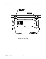
b. Remove the three screws that secure the EMI filter/transient protection circuit cover.
Remove the cover from the chassis.
c. Remove the two nuts that secure the EMI filter to the inside of the chassis rear panel.
d. Remove the DC+ and DC- terminals of the circuit breaker harness from the EMI filter
output (bottom) connections.
e. Remove the CHASSIS GROUND terminal of the circuit breaker harness from the EMI
filter ground connection.
f. Remove the DC+, DC-, and CHASSIS GROUND terminals of the circuit breaker
harness from the power supply terminal block.
g. Remove the nut that secures the circuit breaker to the front panel of the printer.
Remove the circuit breaker assembly from the chassis.
Installation:
a. Position the circuit breaker switch on the front panel. Install the washer and nut that
secure the switch to the panel.
b. Install the DC+, DC-, and CHASSIS GROUND terminals of the circuit breaker harness
on the power supply terminal block.

