background image

v


CAUTION


READ BEFORE CONNECTING INPUT SIGNALS

The data acquisition device you have purchased and are about to use is 

NOT

 an 

ISOLATED

 product. This means 

that it is susceptible to common mode voltages that could cause damage to the device. 

SUCH DAMAGE IS NOT 

COVERED BY THE PRODUCT’S WARRANTY

. Please read the following carefully before deploying the prod-

uct. Contact DATAQ Instruments Support at 330-668-1444 for all questions.

This product can tolerate a maximum applied voltage of only ±20V peak without damage. Although you may be cer-
tain that the signal you want to measure is lower than this level, a common mode voltage (CMV) with an unknown 
value may combine with your signal of interest to exceed this ±20V limit. In such instances, the product will be dam-
aged. Verify a CMV does not exist before connecting signals and acquiring data with your device. Use the following 
procedure to check for CMV:

1.

DO NOT connect your data acquisition device to the device under test. If the device under test is connected to 
your data acquisition device, disconnect it.

2.

Connect your data acquisition device to the appropriate interface on your PC (USB, Ethernet, RS-232 Serial, or 
Parallel Printer Port).

3.

Apply power to your data acquisition device, your PC, and the device under test.

4.

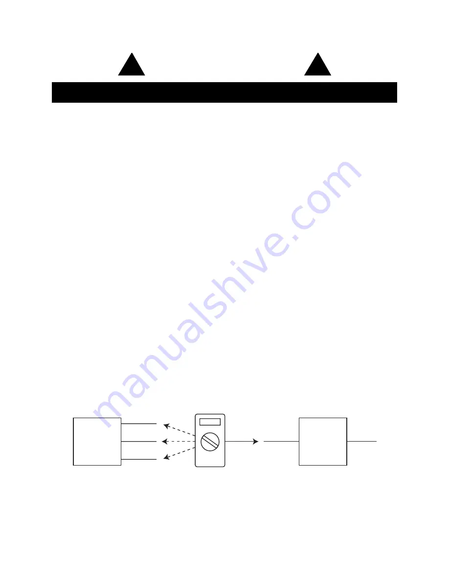
Use a digital voltmeter to make the following measurements:

a.

Measure the voltage (both the AC and DC range) between the ground terminal of your data acquisition 
device and  of the device under test. This measurement should not exceed the Full Scale Range of 
your data acquisition device.

b.

Measure the voltage (both the AC and DC range) between the ground terminal of your data acquisition 
device and Signal- of the device under test. This measurement should be at or very near 0 Volts.

c.

Measure the voltage (both the AC and DC range) between the ground terminal of your data acquisition 
device and Common of the device under test. This measurement should be at or very near 0 Volts.

5.

Should ANY of these measurements exceed their recommendation 

DO NOT CONNECT SIGNALS

 to the data 

acquisition device. A common mode voltage may exist that could destroy the instrument. You MUST determine 
the source of the CMV and eliminate it before taking any measurements.

1

Measured signal is not to exceed the Full Scale Range of your data acquisition device.

2

Measured signal must be at or very near 0 volts.

3

Measured signal must be at or very near 0 volts.

4

Connect to GND (Analog Ground) port on DI-194RS instruments.

!

!

Device

Under

Test

 1

Signal - 

2

Common

3

Digital Voltmeter

Data

Acquisition

Device

To PC

Ground

4

Summary of Contents for DI-194RS

Page 1: ...er language in any form or by any means electronic mechanical magnetic optical chemical manual or otherwise without expressed written authorization from the com pany The distribution of this material...

Page 2: ......

Page 3: ...o products that have been repaired or altered by persons other than DATAQ Instru ments employees or products that have been subjected to misuse neglect improper installation or accident DATAQ Instrume...

Page 4: ......

Page 5: ...3 Apply power to your data acquisition device your PC and the device under test 4 Use a digital voltmeter to make the following measurements a Measure the voltage both the AC and DC range between the...

Page 6: ......

Page 7: ...nd WinDaq Waveform Browser Playback and Analysis Software 1 Help 1 Conventions Used in the Documentation 1 General Conventions 1 Mouse Conventions 1 WinDaq Operating Modes 2 2 Getting Started 3 Connec...

Page 8: ......

Page 9: ...on packages The software s disk streaming design allows data files of any length to be graphically displayed rapidly in normal or reverse time directions Seven standard cursor based measurements frequ...

Page 10: ...operating mode provides access to most data acquisition functions and adjustments includ ing control of the real time display screen s scaling and offset functions The SET UP mode displays data in rea...

Page 11: ...WINDAQ Software 1 Insert the WINDAQ Resource CD into your CD ROM drive and close the drive tray For most users the Win dows auto run feature will automatically display a list of options If you do not...

Page 12: ...This program allows the user to generate a multi channel XY plot in real time The WINDAQ Lite Data Acq DI 194 icon runs the WINDAQ Lite Data Acquisition Software The WINDAQ Waveform Browser icon runs...

Page 13: ...lowing steps 1 Connect a wire between CH1 and GND on the DI 194RS serial port module 2 Select channel 1 by clicking the left mouse button in the channel s annotation margin Channel 1 is enabled for mo...

Page 14: ...11 Enter 10 in the Top Limit text box and 10 in the Bottom Limit text box and click OK 12 Repeat steps 6 through 11 for channels 2 3 and 4 13 From the File menu select Save Default Setup This saves th...

Page 15: ...ignal input CH 2 Channel 2 analog signal input CH 3 Channel 3 analog signal input CH 4 Channel 4 analog signal input Gnd Ground Dig 0 Digital port 0 Dig 1 Digital port 1 Dig 2 Digital port 2 To connec...

Page 16: ...anual Connecting Input Signals 8 When an input signal is connected WINDAQ Lite s real time display immediately reveals the input waveform on your computer s monitor Loosen Tighten Screwdriver Pressure...

Page 17: ......

Page 18: ...Telephone 330 668 1444 Fax 330 666 5434 E mail support dataq com Vertrieb Distributed by ALTHEN GmbH Mess und Sensortechnik Frankfurter Str 150 152 Tel 49 0 6195 7006 0 http www althen de 65779 Kelkh...

Reviews: