DI-1100 Hardware Manual
Controls, Indicators, and Connections
13
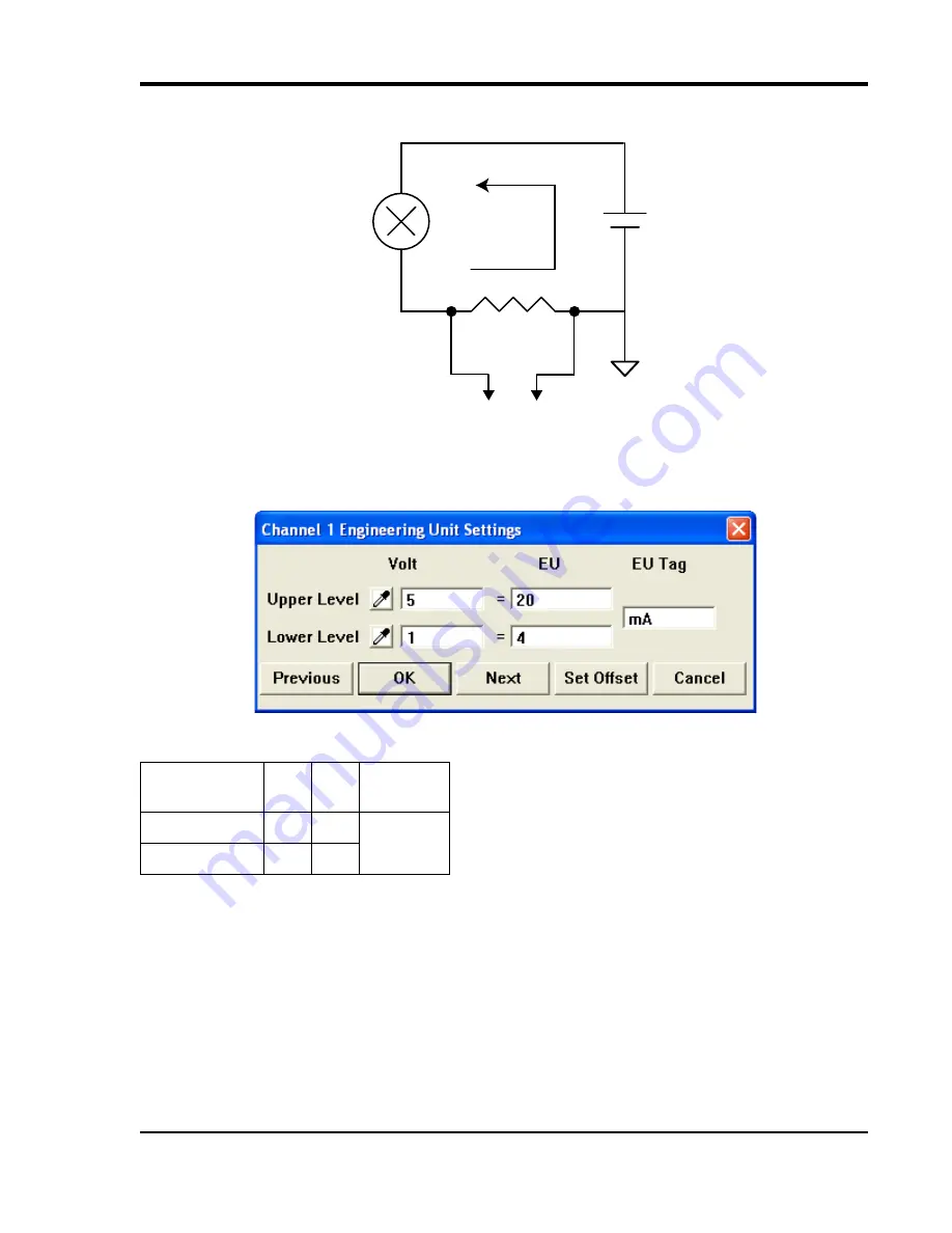
The shunt resistor should be placed on the low side of the circuit as shown below:
Set the engineering units as desired and define upper/lower levels in W
IN
D
AQ
as 1V = 4mA for the low value and 5V
= 20mA for the high value. For example, when using W
IN
D
AQ
Acquisition software, in the EU Settings dialog box:
Enter the following values:
You can also associate these values to a physical measurement such as pressure, load, flow, torque, etc. Read the Help
files for more information regarding Engineering Units Settings.
LED Indicators
The DI-1100 provides three LEDs for instrument status and notification.
Power:
Green LED indicates power is applied via the USB cable.
Active:
Indicates the device is in use either by W
IN
D
AQ
Acquisition Software or a custom user-developed program.
Remote:
Green LED indicates when the Event Button is pushed or the Event terminals are connected via a relay con-
tact or digital input.
Vol
t
EU
EU Tag
Upper Level
5
20
mA
Lower Level
1
4
Shunt Resistor
I
4-20mA
Current Loop
Transmitter
Loop Power
Supply
To DI-1100
Analog Input Channel
+
-


