DI-4730 Hardware Manual
Controls, Indicators, and Connections
14
Rear Panel
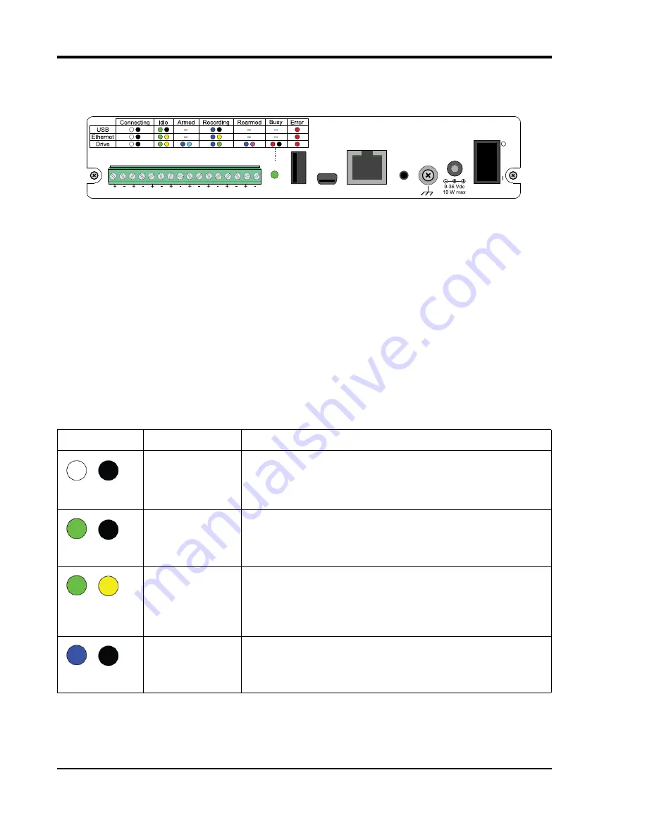
The rear panel of the DI-4730 contains power, communications, and digital inputs.
“Digital Inputs”
Refer to the following for Digital Input pinout:
D#:
Digital port (0-6). Can also be used for specific W
IN
D
AQ
functions (+25 Vmax).
D0 Event
— W
IN
D
AQ
Remote Event Marker (or general-purpose)
D1 Record
— W
IN
D
AQ
Remote Start/Stop (or general-purpose)
D2 Rate
— Rate Input (or general-purpose)
D3 Count
— Counter Input (or general-purpose)
D4
and
D5
— General-purpose digital inputs
D6 Ext Trig
— External Trigger (or general-purpose)
Excitation:
+15V out. Max current = 67mA. Use these ports to power sensors as required.
“Status” LED
Indicates what mode the instrument is in. Use the chart on the top of the instrument for quick reference. Use the table
below for a detailed description of each state as well as a description of some states not displayed on the label.
State
Mode
Description
Connecting
The device is looking for a connection to your PC or USB thumb
drive. It will check the USB interface first, then the Ethernet and USB
thumb drive. Once a connection is established the device will enter
Idle mode.
Blinking White
Idle
USB Connected
The device is connected to and communicating with your PC through
the USB port. The USB thumb drive and Ethernet port are not accessi-
ble.
Blinking Green
Idle
Ethernet or USB
Drive Connected
The device is connected to and communicating with your PC through
the Ethernet port or the device is in Stand-alone mode. The USB inter-
face is not accessible.
Blinking Green/
Yellow
Acquiring Data
to PC via USB
Interface
WinDaq Acquisition Software is running and the device is acquiring
data to your PC via the USB interface.
Blinking Blue
Ethernet
USB
USB Drive
Status
Button
Power
D4
D5
D6
D3
Count
D2
Rate
D1
Record
D0
Event
Digital Inputs (0 - 25V Max)
Excitation


