DI–710 Series and DI-715B Series Hardware Manual
Instrument Controls, Indicators, and Connections
23
Differential inputs occupy two channels with the lowest numbered channel in the pair assuming the positive (+) input
and the channel number. Refer to the following for differential pairs.
For example, to configure Channel 1 as a differential input: Connect Channel 1 as the positive (+) input and channel
9 as the negative (-) input—the pair is referred to as “channel 1 differential.” The following illustration shows chan-
nels 1 and 9 configured as channel 1 differential.
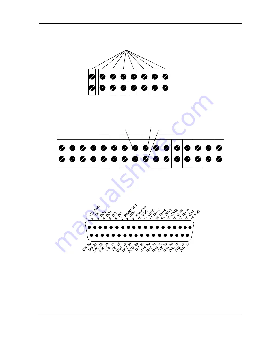
37-pin D sub connector
The two removable 16-port screw terminal blocks may be replaced by a 37-pin D Sub Connector for all DATAQ
Instruments DI-710 Series products (add a “D” to the model number). Refer to the following diagram for pin out.
Note: Digital I/O connections cannot be used concurrently. DI0 and DO0 are directly connected inside the DI-710
(as are DI1 and DO1, DI2 and DO2, etc.).
Refer to “7. Accessories” for accessories that can be used with the 37 pin D sub connector.
1
2
3
4
9
10
11
12
5
6
7
8
13
14
15
16
negative differential channels
positive differential channels
differential pairs
Digital Input/Output
0
1
2
3
4
5
6
7
DG
+5V
R
AG
Analog Channels
1
2
3
4
9
10
11
12
5
6
7
8
13
14
15
16
Channel 1 configured for differential input
Optional Ground (shield)
Signal -


