DI–710 Series and DI-715B Series Hardware Manual
Instrument Controls, Indicators, and Connections
27
Connecting Signals
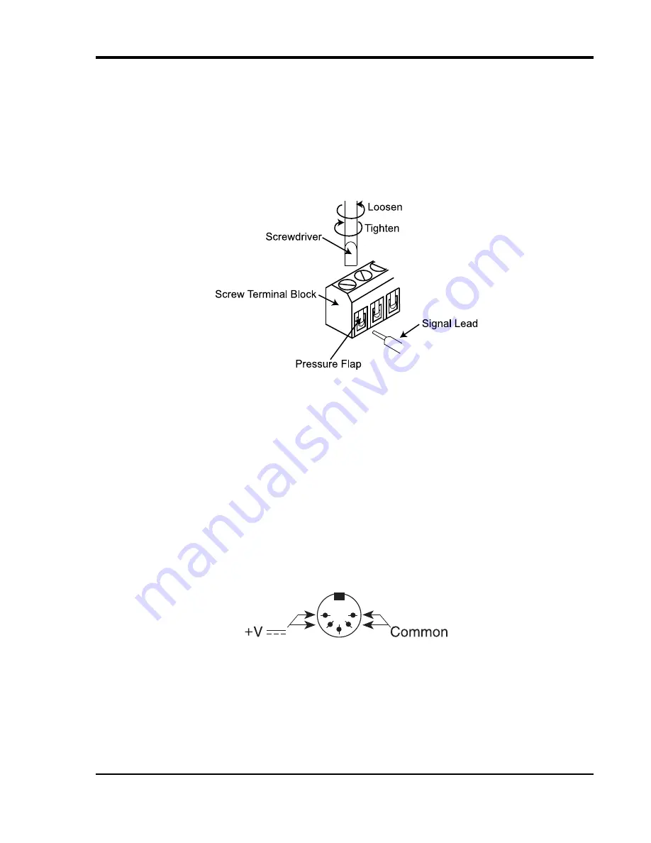
Use the removable screw terminal blocks to connect your signals.
1.
Insert the stripped end of a signal lead into the desired terminal directly under the screw.
2.
Tighten the pressure flap by rotating the screw clockwise with a small screwdriver. Make sure that the pressure
flap tightens only against the signal wire and not the wire insulation.
Do not over-tighten.
3.
Tug gently on the signal lead to ensure that it is firmly secured.
When an input signal is connected and W
IN
D
AQ
Acquisition software is run, W
IN
D
AQ
’s real time display immedi-
ately reveals the input waveform on your computer’s monitor.
Controls and Indicators
Expansion (DI-715B Models)
The Expansion connector may be used to access channels 9-16 by connecting either a DI-705 (adds up to 8 direct
inputs) or a DI-75B (adds up to 8 5B signal conditioned inputs). The Digital I/O may also be accessed through the
Expansion connector using a DI-705. See “The DI-705” on page 42 for more information.
Power Input Jack
For Ethernet models and Stand-alone models. Power must be applied with the included power adapter or with an
alternate appropriate source (9-36 VDC, 2 watts max). External power is not required for DI-710-UH and DI-710-UL
models—Power is derived through one of your PC’s USB ports or through a powered USB hub. If using an alternate
power source with the DI-715B refer to the following for pin out.
Power Switch (DI-715B Models)
Switches power on/off. If power is on the Mode LED will be on.
Ground
This ground lug should always be connected to a solid chassis or earth ground. This connection is mandatory for the
unit to meet CE guidelines.


