DI–720/DI–722/DI–730 Series User Manual
Getting Started
26
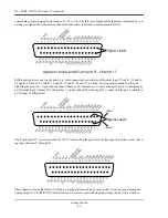
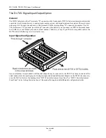
conditioning-required signals in the range of ±1.25 to ±10 volts full scale. Single-ended inputs are configured by con-
necting one signal lead to the desired channel and the other signal lead to analog ground (AGD):
Differential inputs occupy two channels (e.g., these channel pairs constitute a differential input: 17 and 25, 18 and 26,
19 and 27, 20 and 28, 21 and 29, 22 and 30, 23 and 31, 24 and 32), with the lowest numbered channel in the pair
assuming the positive (+) input and the channel number. For example, say we have channels 18 and 26 configured as
a differential input. Channel 18 is the positive (+) input, channel 26 is the negative (-) input, and the pair is referred to
as “channel 18 differential.”
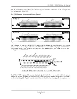
The 37-pin male “D” connector on the DI-722-16 (labeled B in the graphic of the front panel) provides access to ana-
log input channels 17 through 32
This connector also includes DAC1, which is a second digital-to-analog converter that serves as a general purpose
analog output; R. START/STOP, which allows you to remotely start and stop data storage to disk with a switch or
Signal Leads
+ input
- input
Summary of Contents for DI-725/E
Page 2: ......
Page 4: ......
Page 6: ......
Page 10: ......
Page 32: ......
Page 40: ......
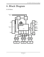
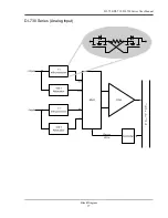
Page 45: ...DI 720 DI 722 DI 730 Series User Manual Block Diagram 35 6 Block Diagram DI 720 Series 1 32...
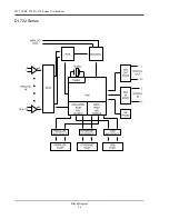
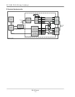
Page 46: ...DI 720 DI 722 DI 730 Series User Manual Block Diagram 36 DI 722 Series...
Page 106: ......
Page 107: ......

