DI–720/DI–722/DI–730 Series User Manual
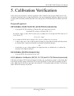
Calibration Verification
34
Offset Calibration Verification (DI-730 Instruments only)
1.
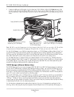
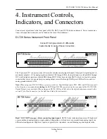
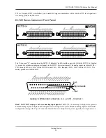
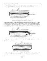
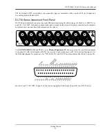
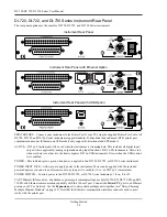
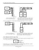
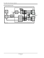
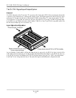
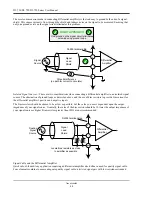
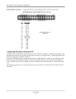
Connect your voltage calibrator, or combination DVM and voltage source to your DI-730 instrument as shown
above. Apply zero volts to the instrument (or short the instrument's analog channel input to ground).
2.
Open the W
IN
D
AQ
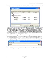
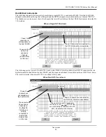
/Lite/Pro/Pro+ data acquisition screen. Enable the channel you want to verify. Enable a maxi-
mum burst sample rate of 50,000 Hz by selecting EDIT-PREFERENCES-MAX SAMPLE RATE. Enable a
W
IN
D
AQ
sample rate of 50 Hz. Set the Acquisition Mode to AVERAGE select the 10mV range through
W
IN
D
AQ
's CHANNEL SETTINGS menu for the selected channel.
3.
Referring to W
IN
D
AQ
software's voltage display for the channel you're evaluating, compare this value to that
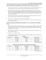
given in the OFFSET column of TABLE (2) for the selected range.
4.
Repeat steps 2 and 3 using for each measurement range.
5.
Select the next channel, and repeat steps 2 through 4.
6.
If any readings are out of the acceptable ranges described in TABLE (2) arrange to have your instrument recali-
brated by DATAQ Instruments.
Full Scale (Span) Calibration Verification (DI-730 Instruments Only)
1.
Referring again to TABLE (2) select the 10mV range and apply the voltage indicated by the SPAN VOLTAGE
column of TABLE (2) to the selected channel.
2.
Verify the reading by comparing the value displayed by W
IN
D
AQ
software with the value of TABLE (2) in the
SPAN ACCURACY column.
3.
Repeat steps 1 and 2 for all ranges.
4.
Repeat steps 1 through 3 for all channels.
5.
If any readings are out of the acceptable ranges described in TABLE (1) arrange to have your instrument recali-
brated by DATAQ Instruments.
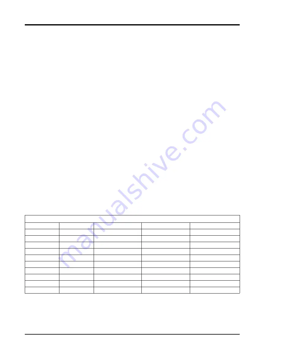
TABLE (2
)
Channel Group
Range
Offset @ 0V
Span Voltage
Span Accuracy*
1 through 8
10mV
0 ±0.04mV
9mV
9mV ±0.025mV**
100mV
0 ±0.4mV
90mV
90mV ±0.25mV**
1V
0 ±4mV
900mV
900mV ±2.5mV
10V
0 ±10mV
9V
9V ±25mV
100V
0 ±100mV
90V
90V ±250mV
1000V
0 ±1V
700V
700V ±2.5V
17 through 32
10V
0 ±5mV
9V
9V ±25mV
5V
0 ±3mV
4.5V
4.5V ±12.5mV
2.5V
0 ±2mV
2V
2V ±6.25mV
1.25V
0 ±1mV
1V
1V ±3.125mV
*Excludes offset errors.
** These low-level measurements require an environment free from electrical noise.
Summary of Contents for DI-725/E
Page 2: ......
Page 4: ......
Page 6: ......
Page 10: ......
Page 32: ......
Page 40: ......
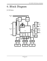
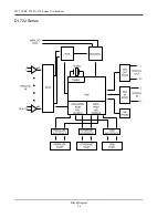
Page 45: ...DI 720 DI 722 DI 730 Series User Manual Block Diagram 35 6 Block Diagram DI 720 Series 1 32...
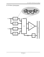
Page 46: ...DI 720 DI 722 DI 730 Series User Manual Block Diagram 36 DI 722 Series...
Page 106: ......
Page 107: ......

